Administrator’s Guide(CP45FV) Eng.pdf - 第157页
S tep Pr ogramming 9-5 shafts of the X, Y-axes driving motors or to obtain the current shaft locations of the X, Y-axes driving motors. <Device> combo box Used to select the corresponding device when mo…
Samsung Component Placer CP45FV Series Administrator’s Guide
Position Y: Displays the Y position of the current placement point.
<Adjust> check box
Displayed only when the fiducial mark has been set.
To move after adjusting by using the fiducial mark of the PCB, check this check
box.
<Find> group
Edit box
Set the string of characters to find. At this time, the column in the grid containing
the string of characters must be specified first.
<Find Prev>
button
Finds the string of characters set in the edit box in the previous lines of the
current line of the column specified in the grid.
<Find Next>
button
Finds the string of characters set in the edit box in the next lines of the current
line of the column specified in the grid.
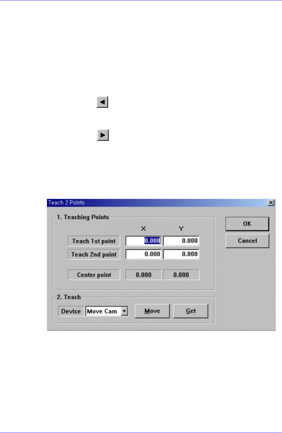
<2Pt. Teach> button
When a placement position is set, performs the function of teaching 2 corner points,
calculating the center point and using it as the placement point. When this button is
clicked on, the following dialog box is displayed.
Figure 9-2. “Step: Teach 2 Points” dialog box
<1. Teaching Points> group
Set the positions of two corner points to obtain the center point.
Teach 1st point: Set the position of the first point.
Teach 2nd point: Set the position of the second point.
Center point: Displays the center point by using the positions of two corner
points.
<2. Teach> group
Used to move the head assembly or spindle to the set position by rotating the
9-4

Step Programming
9-5
shafts of the X, Y-axes driving motors or to obtain the current shaft locations of
the X, Y-axes driving motors.
<Device> combo box
Used to select the corresponding device when moving the head assembly by
rotating the shafts of the X, Y-axes driving motors or to obtain the current
coordinate of the device to be selected. Available devices are as follows;
Move Cam: Selects Teaching Camera.
Head1: Selects Head1.
Head2: Selects Head2.
Head3: Selects Head3.
Head4: Selects Head4.
Head5: Selects Head5.
Head6: Selects Head6.
Beam: Selects Beam.
<Move> button
Moves the head assembly by rotating the shafts of the X, Y-axes driving motors
using the device selected from the <Device> combo box. Before executing
“Move”, the edit box corresponding to the desired position must be clicked on
with a mouse.
<Get> button
Reads in the current position of the XY axis of the device selected in <Device>.
Before executing “Get”, the edit box corresponding to the desired position must
be clicked on with a mouse.
<OK> button
Sets the obtained center point as the new pickups point and closes the dialog box.
<Cancel> button
Ignores the obtained center point and closes the dialog box.
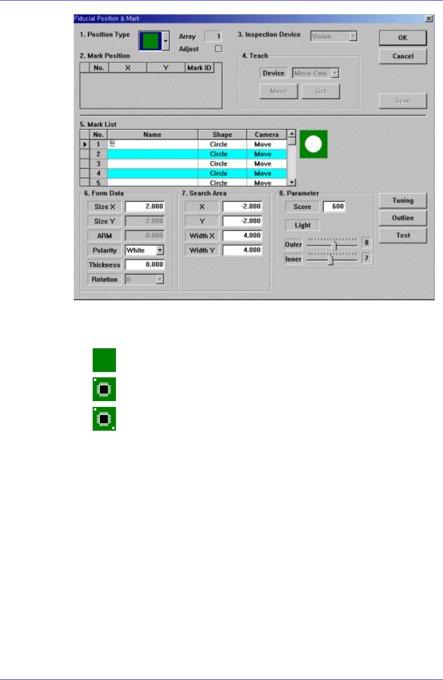
<Fiducial…> button
If the placement point has a fiducial mark, sets the fiducial mark data. When this
button is clicked on, the following dialog box is displayed.
Samsung Component Placer CP45FV Series Administrator’s Guide
<Position Type> combo box
Select the number of fiducial marks. Available numbers of fiducial marks are as
follows.
None: No fiducial mark.
1 Part: 1 fiducial mark for placement point adjustment.
2 Part: 2 fiducial marks for placement point adjustment.
For the rest, please refer to the explanation of the <Fiducial Mark…> button in
<11.1 Board>.
<Offset…> button
Adds the offset value to the position of placement point. Before executing this
function, X column or Y column or Z column or R column or the line to add the
offset value must be selected in the grid. When this button is clicked on, the following
dialog box is displayed.
9-6