Administrator’s Guide(CP45FV) Eng.pdf - 第121页
Part Registration 7-37 7.4.1. Lead Parameter Set the lead parameter for User ICs. Possible lead parameters are up to 8. Figur e 7-25. Screen showing “ Lead Parameter ” setting in the dialog box for “ User IC Lead Paramet…

Samsung Component Placer CP45FV Series Administrator’s Guide
gray level image is converted into binary, it is the value used as the criteria to
determine black and white.
The value range is 0 – 255(0: black, 255: white), and this value serves to
differentiate the component from the background. When the set value is 0,
the value is set automatically during component recognition.
<Auto Threshold> check box
Check it to set the <Threshold> value automatically.
<Binary> button
Displays the binary image of the component on the Vision Monitor screen.
<Repeat Angle> edit box
In the case of the work needed for high precision, this re-recognizes and pick-up
and placement of the component by performing correction according to the
vision recognition result. For example, if o.i is inputted for the repeat angle, it
corrects the angle after vision recognition and re-recognizes it. If the result of re-
recognition is greater than 0.1 it recognizes the angle after correcting the angle. It
repeats this until the result of the recognition become less than 0.1. When the
value becomes 0.1, it pick and place the component (it tries recognition up to 4
times)
<Outline> button
Displays the outline of the component on the vision monitor by using the set align
data.
<Move…> button
Performs component pickups or moves to the fix camera. Please refer to “7.2.1.1
Common Align Data (Page 7-9)” for more information.
<Test> button
Performs the component recognition test by using the set align data. Please refer to
“7.2.1.1 Common Align Data (Page 7-9)” for more information.
<Image Capture> button
Helps to specify the optimum lighting value. The lighting is gradually changed
automatically and the images are saved. The user can check the best image and
identify the optimum lighting value.
Please refer to “7.2.1.1 Common Align Data (Page 7-9)” for more information.
7-36
Part Registration
7-37
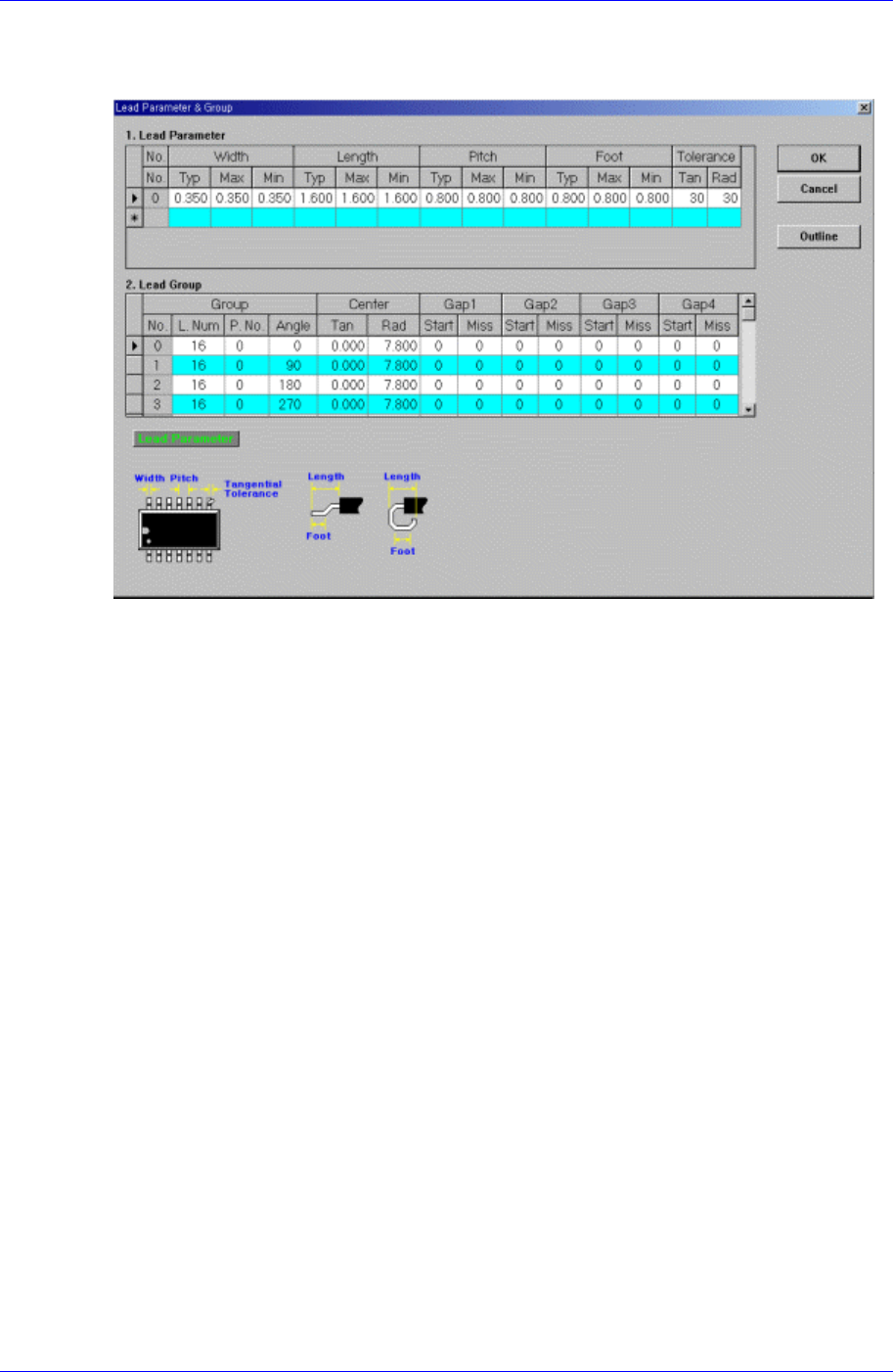
7.4.1. Lead Parameter
Set the lead parameter for User ICs. Possible lead parameters are up to 8.
Figure 7-25. Screen showing “Lead Parameter” setting in the dialog box for “User IC Lead
Parameter & Group “
<Lead Parameter> group
Set the lead parameter.
<No.> column
Displays the lead parameter number. Possible range is 0 – 7.
<Width Typ> column
Set the lead width.
<Width Max> column
Set the lead width including the highest tolerance.
<Width Min> column
Set the lead width including the lowest tolerance.
<Length Typ> column
Set the lead length.
<Length Max> column
Set the lead length including the highest tolerance.
<Length Min> column
Set the lead length including the lowest tolerance.
<Pitch Typ> column
Set the lead pitch, which is the length from the center of the lead to the center of
the adjacent lead.
<Pitch Max> column
Set the lead pitch including the highest tolerance.
Samsung Component Placer CP45FV Series Administrator’s Guide
<Pitch Min> column
Set the lead pitch including the lowest tolerance.
<Foot Typ> column
Set the length of the lead that touches the surface.
<Foot Max> column
Set the lead foot including the highest tolerance.
<Foot Min> column
Set the lead foot including the lowest tolerance.
<Tolerance Tan> column
Set the allowable tolerance when the lead is bent to the side. Set it as a
percentage of <Lead Pitch>
<Tolerance Rad> column
Set the allowable tolerance for lead length. Set it as a percentage of <Lead
Length>.
<Outline> button
Displays the outline of the component on the vision monitor by using the set align
data.
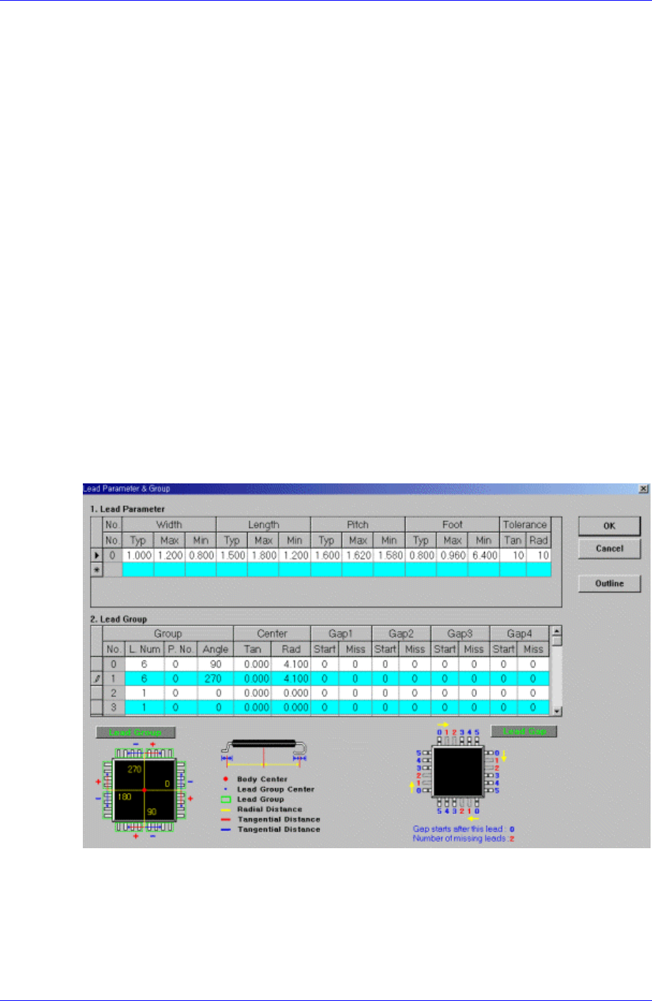
7.4.2. Lead Group
Set the lead group for User IC. Up to 16 lead groups can be set.
Figure 7-26. Screen showing “Lead Group” setting in the dialog box for “User IC Lead
Parameter & Group”
<Lead Group> group
Set the lead group.
<Group No.> column
7-38