Administrator’s Guide(CP45FV) Eng.pdf - 第174页
Samsung Component Placer CP45FV Series Administrator ’ s Guide Point> option performs a mounting ope ration for PCBs 1, 2, 3, and 4 at the same time. In general, the latter method can increase overall operation ef fic…
Optimization
10-7
10.5. Setup Menu/Parameters
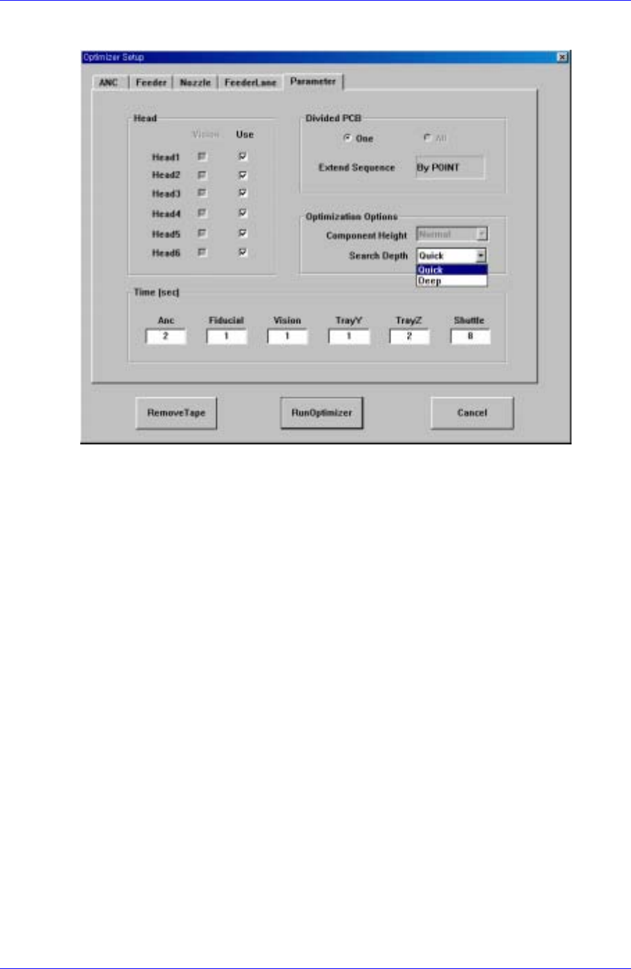
Figure 10-6. "Optimizer Setup: Parameters" dialog box
Lastly, the screen to set the options and parameters for the Optimizer execution.
<Head> check box group
components. Check the vision check box when the vision arranged components in the
corresponding head are to be operated. For full vision equipment like CP45F/V NEO
model, check all the vision check boxes. The use check box indicates whether to use
the corresponding head. For example, if there is a problem with Head3 and it is
difficult to operate, click on the use check box for Head3 and leave it blank. Then the
Optimizer creates an operation program without using the prohibited head. When all
the heads are prohibited, an error message is displayed immediately when the
Optimizer is executed.
<Divided PCB> box group
Used to specify optimization options and display method of the MMI step program
when the Array PCB is edited. The Array PCB can have only one unit PCB displayed
in the step program and have the same operation repeated for each PCB or have the
step program for the whole PCBs be displayed. This can be selected in the step edit
screen of the MMI. When the former is selected, it is indicated in the <One> button in
the <Divided PCB> box, and the latter is indicated in the <All> button.
The <Extended Sequence> combo box in the <Divided PCB> box is activated only
when <All> is selected. Optimization method for Array PCBs in the Optimizer is
decided here. When <By PCB> is selected, the Optimizer creates a step program so
that an optimization program for a unit PCB is created and applied to other PCBs in
sequence. On the other hand, when <By Point> is selected, all PCBs are considered
as one and an optimization program for all placement points is created. For example,
in the case of an array PCB consisting of 4 PCBs, the <By PCB> option completes an
operation for a PCB and then starts an operation for the next PCB, while the <By

Samsung Component Placer CP45FV Series Administrator’s Guide
Point> option performs a mounting operation for PCBs 1, 2, 3, and 4 at the same time.
In general, the latter method can increase overall operation efficiency. However, if
there are many defective PCBs, the operation efficiency might be lower than the
former.
<Optimization Options> group
The group to set options for the optimization algorithm itself executed by the
Optimizer.
In general, shorter components should be mounted earlier than taller components. If
this order is not followed, some of the PCBs might bump into the components with
nozzle installation. The <Component Height> option decides how closely this rule is
to be followed. If this rule is too strictly applied unnecessarily, a low efficiency
program might be generated. For regular PCBs, select <Normal>, and for the PCBs
that need a strict application of this rule, select <Strict>.
The <Search Depth> option is used to decide the execution method of mounting order
algorithm. It is because the optimization of mounting order takes the longest in the
Optimizer execution time in general. In addition, the more the placement points, the
longer the Optimizer execution time. When <Quick> is selected, the mounting order
can be decided quickly. In general, however, operation efficiency in the end is lower
than when <Deep> is selected. To raise the operation efficiency, select <Deep>
although the Optimizer execution time is longer. These options do not affect the
arrangement of nozzles or feeders.
<Time(sec)> edit box group
This group is to enter the time needed to execute each motion of equipment, it is used
to calculate the operation time in the Optimizer. The values of Tray Y and Tray Z can
affect the decision of operation order. Therefore, enter a value closest to the actual
value to increase operation efficiency and accuracy of operation time estimation.
ANC: time needed for one nozzle change operation (sec)
Fiducial: time needed to recognize a fiducial mark (sec)
Vision: time needed to recognize a vision component at the fixed camera (sec)
Tray Y: time needed for a tray in the Multi-Tray Feeder to move in Y direction
(sec)
Tray Z: time needed for a tray in the Multi-Tray Feeder to move in Z
direction(sec)
Shuttle : Time needed for the Shuttle Tray pad to move back and forth (sec)
10-8
Optimization
10-9
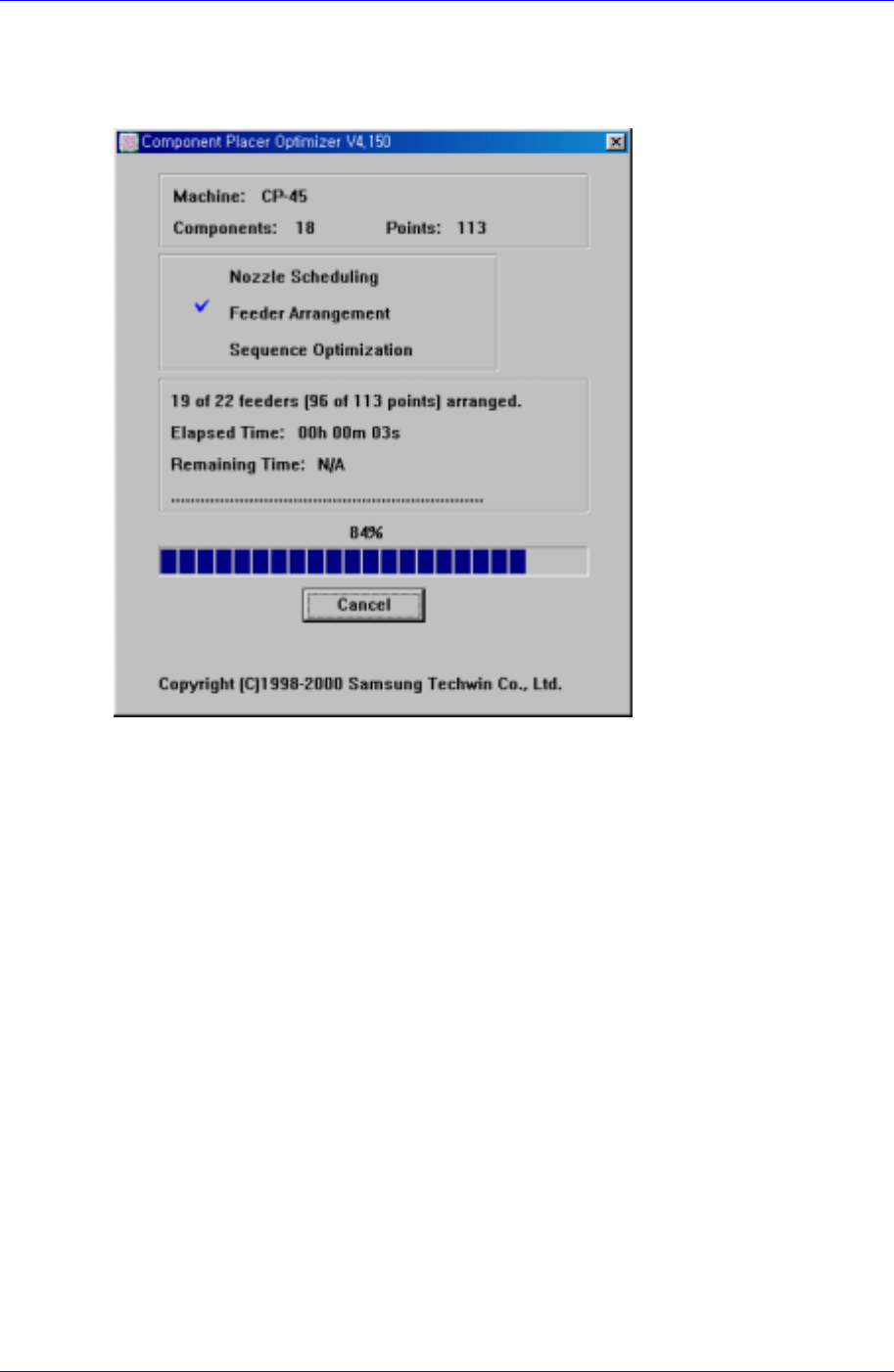
10.6. Optimizer Dialog
Press the <Run Optimizer> button to execute the Optimizer. During the execution, the
following dialog box is displayed.
Figure 10-7. "Optimizer" dialog box
In the top box, equipment model name, the number of component types, and total
placement points are displayed. In the second box, the steps of Optimizer progression are
displayed with a check mark. The one with the check mark is the step in progress. In the
third box, more detailed progression status, elapsed time and remaining time are
displayed. Remaining time is displayed only in the sequence optimization step when the
search depth option is set to Deep. The more the number of component types and
placement points, the longer the execution time. The progress bar under the third box
shows the progress of the current step. The Cancel/Stop button on the bottom is used to
stop the execution of Optimizer in the middle. Normally Cancel is shown on the button,
when this button is pressed in this status, the User Break message box is displayed and
the Optimizer execution is cancelled. In other words, all the operation executed thus far is
cancelled. However, if Deep is selected for the search depth in the Optimizer execution
option, Stop is displayed during sequence optimization. At this time, even though this
button is pressed, the optimization solution searched so far is preserved and a dialog box
according to this result is displayed. When the Accept button is clicked on here, a step
program based on the optimization solution searched so far is created.