Administrator’s Guide(CP45FV) Eng.pdf - 第87页
Part Registration 7-3 Displays the nozzle that pick up com ponents. The nozzle types are as follows. TN-04S, TN03, TN04, TN065, TN 14, TN22, TN40, TN75, TN110 <Nozzle2> column Displays the auxiliary nozzle …
Samsung Component Placer CP45FV Series Administrator’s Guide
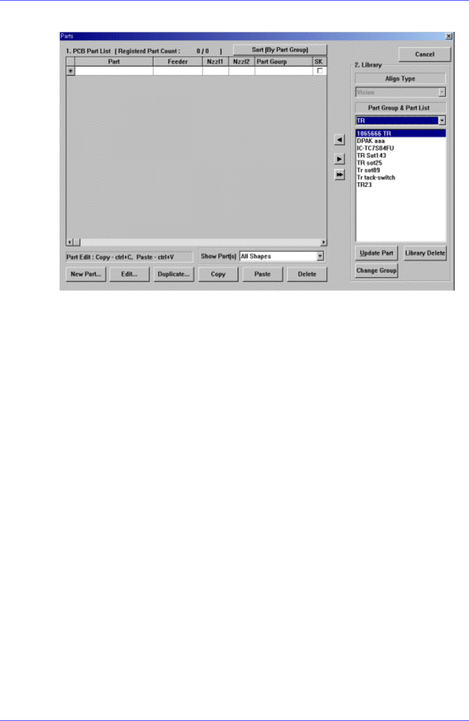
When the <Part> command is selected, the initial screen is as follows.
Figure 7-3. “Parts” dialog box
<1. PCB Part List> group
Display a list of currently registered components.
<Part> column
Displays the component name.
<Feeder> column
Displays the type of the feeder supplying components. The types of feeders are
as follows.
8mm Tape: Supply by 8mm Tape Feeder.
12mm Tape: Supply by 12mm Tape Feeder.
16mm Tape: Supply by 16mm Tape Feeder.
24mm Tape: Supply by 24mm Tape Feeder.
32mm Tape: Supply by 32mm Tape Feeder.
44mm Tape: supply by 44mm Tape Feeder.
56mm Tape: Supply by 56mm Tape Feeder.
32mm Adhensive: Supply by 32mm Adhesive Tape Feeder.
Belt Stack Stick: Supply by Belt Stack Stick Feeder.
Vibration Multi Stick: Supply by Vibration Multi Stick Feeder.
Belt Multi Stick: Supply by Belt Multi Stick Feeder.
Single Tray: Supply by Single Tray Feeder.
FW-20F: Supply by 20-stage Tray Feeder.
FW-20S: Supply by 20-stage Tray Feeder.
FW-12M: Supply by 12-stage Tray Feeder
<Nozzle1> column
7-2
Part Registration
7-3
Displays the nozzle that pick up components. The nozzle types are as follows.
TN-04S, TN03, TN04, TN065, TN14, TN22, TN40, TN75, TN110
<Nozzle2> column
Displays the auxiliary nozzle that adsorbs components. When the main nozzle
can not be used, the auxiliary nozzle is used. The types of auxiliary nozzles are
the same as the main nozzle.
<Part Group>
Displays the component Part Group.
<SK>
When it is checked, this part is skipped during placing
<New Part…> button
Registers new component. When this button is clicked on, the following dialog box is
displayed.
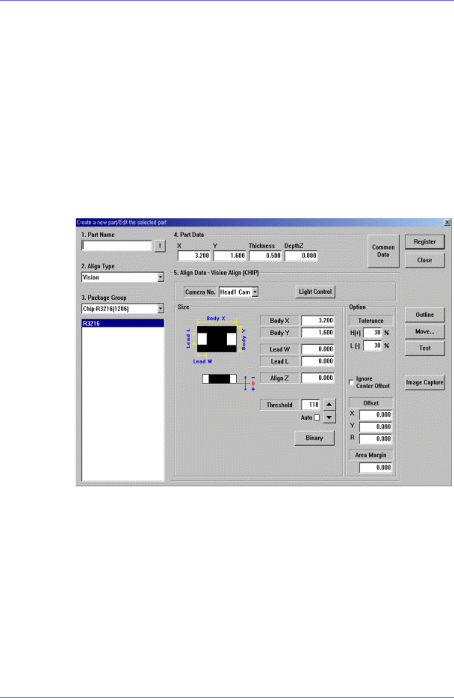
Figure 7-4. “Create a new part/Edit the selected part” dialog box
<1. Part Name> edit box
Set the component name. Ensure that the component name having more than 32
Alphabet characters (16 characters in Korean) is not entered.
(When using the “Duplicate” function or when importing component information
from another PCB file.)
<2. Align Type> combo box
Select the align type.
<3. Package Group> combo box
Select the component group.
<Package List> list box
Displays the component data list selected in <2. Align Type> and <3. Package
Samsung Component Placer CP45FV Series Administrator’s Guide
Group>.
<4. Part Data> group
Set the data including the component size.
<X> edit box
Set the component size in X direction.
<Y> edit box
Set the component size in Y direction.
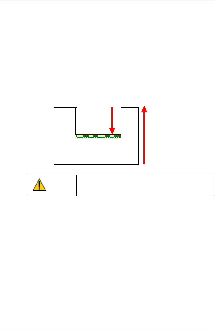
<Thickness> edit box
Set the height(thickness) of the component.
<DepthZ> edit box
Set the depth of the groove on top of the component. Unless warranted by a
special purpose, set to “0”.
Thickness
DepthZ
Pickup Surface
Caution
When the component height is incorrect, the placement
may become less accurate. Input the component height
accurately.
<5. Align Data> group
Set the component align data.
The edit screen for the align data selected in <2. Align Type> and <3. Package
Group> are displayed in this group.
If “None” has been selected in <2. Align Type>, the edit screen is not displayed
since it is a case of not aligning components. If “Vision” has been selected in <2.
Align Type>, the displayed screen differs according to the selected data in <3.
Package Group>.
The screens displayed according to the selected data in <3. Package Group> are
to be explained in the next chapter.
<Common Data> button
Sets the component data related to the machine. When this button is clicked on,
the following dialog box is displayed and the name of the button is changed to
“Align Data”.
“Align Data” button displays the align data screen.
7-4