Administrator’s Guide(CP45FV) Eng.pdf - 第90页
Samsung Component Placer CP45FV Series Administrator ’ s Guide Part Size X at the time of synchronized pick up. <Sync Pick Y> Set the allowance in Y direction as a percentage of Part Size Y at the time of synchroni…

Part Registration
7-5
Figure 7-5. “Create a new part/Edit the selected part- Common Data” dialog box
<Feeder & Nozzle> group
<Feeder> combo box: Select the feeder type to supply components.
Applicable feeder types are as follows.
8mm Tape: Supply by 8mm Tape Feeder.
12mm Tape: Supply by 12mm Tape Feeder.
16mm Tape: Supply by 16mm Tape Feeder.
24mm Tape: Supply by 24mm Tape Feeder.
32mm Tape: Supply by 32mm Tape Feeder.
44mm Tape: supply by 44mm Tape Feeder.
56mm Tape: Supply by 56mm Tape Feeder.
32mm Adhensive: Supply by 32mm Adhesive Tape Feeder.
Belt Stack Stick: Supply by Belt Stack Stick Feeder.
Vibration Multi Stick: Supply by Vibration Multi Stick Feeder.
Belt Multi Stick: Supply by Belt Multi Stick Feeder.
Single Tray: Supply by Single Tray Feeder.
FW-20F: Supply by 20-stage Tray Feeder.
FW-20S: Supply by 20-stage Tray Feeder.
FW-12M: Supply by 12-stage Tray Feeder
<Nozzle1> combo box: Displays the nozzle that pick up the component. The
types of nozzles are as follows;
(TN-04S, TN03, TN04, TN065, TN14, TN22, TN40, TN75, TN110)
<Nozzle2> combo box: Displays the auxiliary nozzle that adsorbs the
component. When the main nozzle can not be used, the auxiliary nozzle is
used. The types of auxiliary nozzles are the same as the main nozzle.
<Etc> group
<Sync Pick X> edit box: Set the allowance in X direction as a percentage of
Samsung Component Placer CP45FV Series Administrator’s Guide
Part Size X at the time of synchronized pick up.
<Sync Pick Y> Set the allowance in Y direction as a percentage of Part Size
Y at the time of synchronized pick up.
<Retry> combo box: Set the number of retries when the component pickups
was not successful. Available numbers are 1 - 3.
<Vacuum Check> check box: Check it to carry out vacuum check during
component pickups.
<Delay> group
Set various delay time for pickups, placement, and dump operations.
<Pick Up> edit box: During component pickups, the delay time after the
head has come down until the head starts ascending.
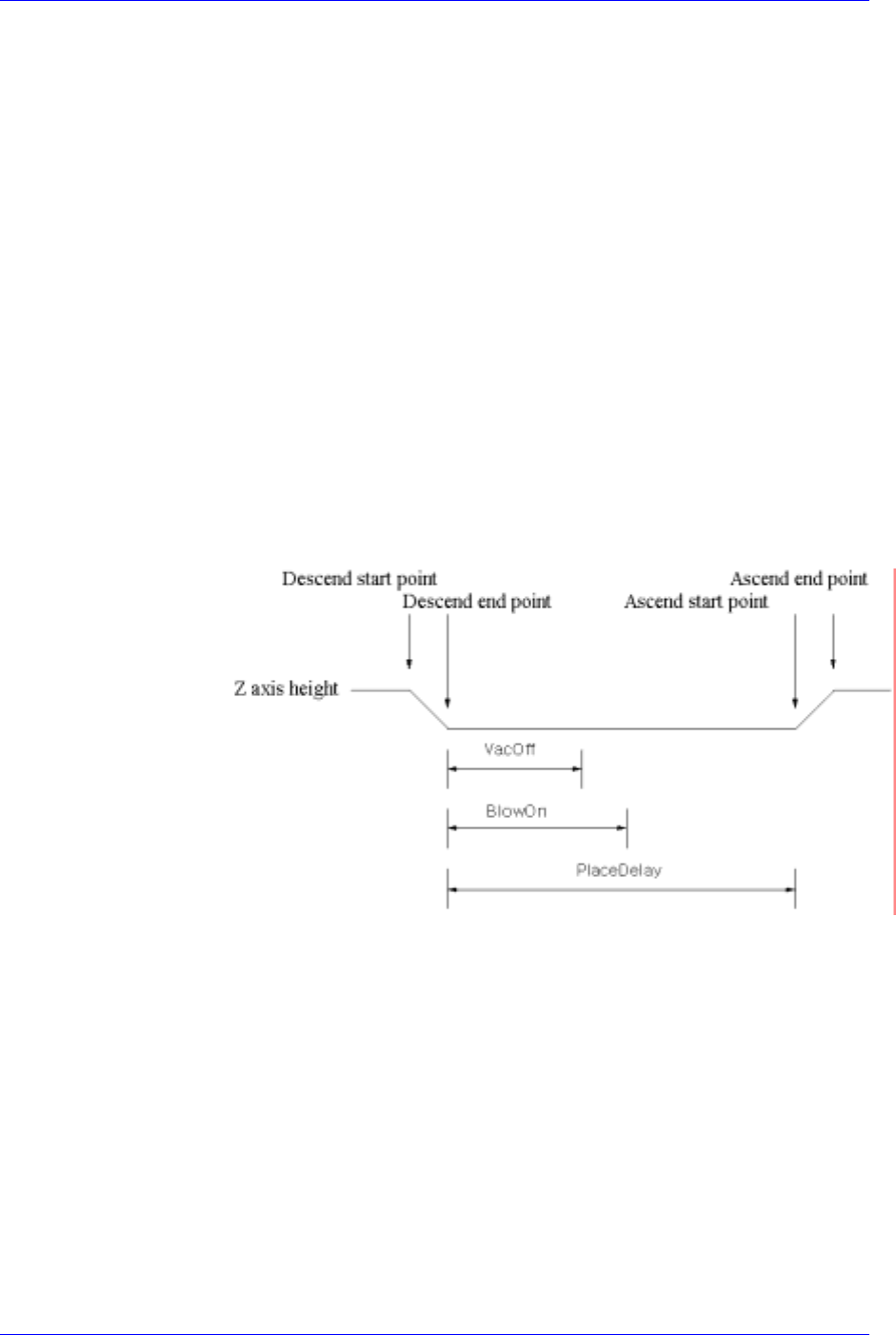
<Place> edit box: During component placement, the delay time after the
head has come down until the head starts ascending.
<Vac Off> edit box: During component placement, the delay time after the
head has come down until vacuum is off.
<Dump> edit box: During component dumping, the delay time after the head
has come down until the head starts ascending.
<Dump Vac Off> edit box: During component dumping, the delay time after
the head has come down until vacuum off.
Figure 7-6. Flowchart of “Delay Time during Placement”
<Speed> group
Set the speed for each axis during pickups, placement, and dumping
operations. The speeds are as follows, and the profile of each moving speed
is set in the system.
1- Fastest: The fastest speed.
2- Fast: Fast speed.
3- Middle: Middle speed.
4- Slow: Slow speed.
5- Slowest: The slowest speed.
<XY> combo box: Select the speed for XY axis
<R> combo box: Select the speed of R axis.
7-6
Part Registration
7-7
<Z Pick Down> combo box: Select the speed for Z axis when the head is
lowered for component pickups.
<Z Pick Up> combo box: Select the speed for Z axis when the head is
ascending after component pickups.
<Z Place Down> combo box: Select the speed for Z axis, when the head is
lowered for placement.
<Z Place Up> combo box: Select the speed for Z axis, when the head is
ascending after placement.
Caution
In case of shock sensitive components like CSP or μBGA,
the z-axis related speed parameters must be set according
to the component manufacturer’s specification or
standards. And use the nozzle suitable to component
manufacturer’s specification or standards.
If necessary, please contact our Business Department or
the local agent for the nozzle suitable to component
manufacturer’s specification or standards.
<Register> button
Adds the set component data to the PCB part list.
<Close> button
Closes the dialog box.
<Edit…> button
Edits the selected component data.
<Duplicate…> button
Copies the selected component data. At this time, new component name must be
set.
<Copy> button
Copies the part data selected from the Part list box.
<Paste> button
Pastes the copied part data to the Part list box.
<Delete> button
Deletes the part selected in the Part list box.
<2. Library> group
Display the component list of the Local Part DB managed by the machine.
<Align Type> combo box
Select the align type of the component to be displayed. The Vision Align is used
as default.
Vision: Alignment by the Vision Camera.
<Part Group> combo box
Select the group of component to be displayed. Available component groups are
as follows.
(CHIP-Circle:, CHIP-Rect:, Melf:, TR:, Trimmer:, Hemt:, SOP:, SOJ:, SOP2:,
SOJ2:, QFP:, PLCC:, Connector-1:, Connector-2:, User IC:, BGA: )
<Part List> list box