Administrator’s Guide(CP45FV) Eng.pdf - 第141页
Feeder Setup 8-9 When the stick feeder is installed in the corresponding slot, set the Z position to pick up the component supplied from the stick feeder. <R> column When the stick feeder is installed in …
Samsung Component Placer CP45FV Series Administrator’s Guide
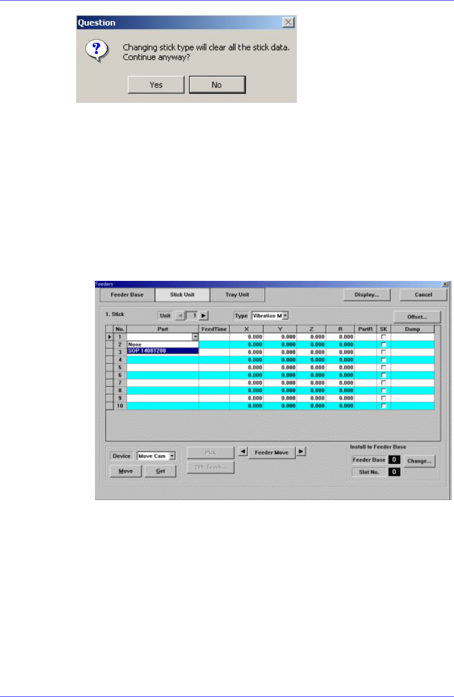
<Stick> group
Create and edit data according to the stick unit type selected in the <Type> combo
box. If “Multi Stick” is selected for <Type>, the following dialog box is displayed.
<No> column
A serial number of the stick unit slots. Basically, “Stack Stick” has 1, “Multi
Stick” has 10 slots.
<Part> column
Select the part to install in the corresponding slot. When the <Part> column is
clicked on, a combo box is displayed, and of the components registered in <1.2
Part>, a list of parts to be supplied to “Stick” are displayed. Select the component
to install in this list. Next is a screen showing component selection in the combo
box of <Part> column.
<FeedTime> column
When a stick feeder is installed in the corresponding slot, set the component
supply time of the stick feeder. Basically stick feeders are vibration type,
therefore certain time interval is necessary after a component is picked up until
the next component moves to the pickups position. The time is set here.
<X> column
When the stick feeder is installed in the corresponding slot, set the X position to
pick up the component supplied from the stick feeder.
<Y> column
When the stick feeder is installed in the corresponding slot, set the Y position to
pick up the component supplied from the stick feeder.
<Z> column
8-8
Feeder Setup
8-9
When the stick feeder is installed in the corresponding slot, set the Z position to
pick up the component supplied from the stick feeder.
<R> column
When the stick feeder is installed in the corresponding slot, set the R
position(rotation angle of the head) to pick up the component supplied from the
stick feeder.
<PartR> column
When the stick feeder is installed in the corresponding slot, set the placement
angle of the component supplied from the stick feeder.
<SK> column
When the stick feeder is installed in the corresponding slot, select whether or not
to pick up the component supplied from the stick feeder.
To pick it up, leave the check box as it is, and not to pick it up, check the check
box.
<Dump> column
When the stick feeder is installed in the corresponding slot, select the dump box
for the component placed on the stick feeder. Available dump boxes are as
follows.
System Dump: The dump box set in the system, it is installed in the front of the
conveyor.
User Dump: The dump box set in the system by the user, the location should be
set in the system..
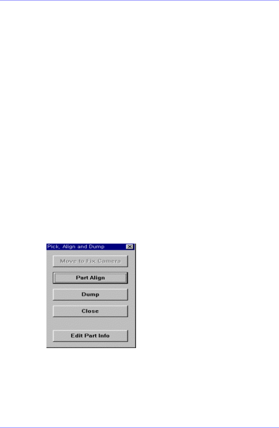
<Pick> button
Executes component pickups operation from the stick feeder installed on the current
line in the grid. At this time, the device must be selected first. When pickups is
successful, the following dialog box is displayed.
<Move to Fix Camera> button
It is activated only when the corresponding component is aligned by the vision
camera and the align camera is fix camera. When this button is clicked on, moves
the head block to the position of the fix camera.
<Part Align> button
Executes alignment of the corresponding component.
<Dump> button
Samsung Component Placer CP45FV Series Administrator’s Guide
Dumps the corresponding component to the dump box.
<Close> button
Closes the dialog box.
<Feeder Move> button
Moves the cursor only to the grid area in which the feeder is mounted.
<Move Prev>
button
Moves the selected device to the slot on the first line with stick feeder installation
among the lines before the current line in the grid.
<Move Next>
button
Moves the selected device to the slot on the first line with stick feeder installation
among the lines after the current line in the grid.
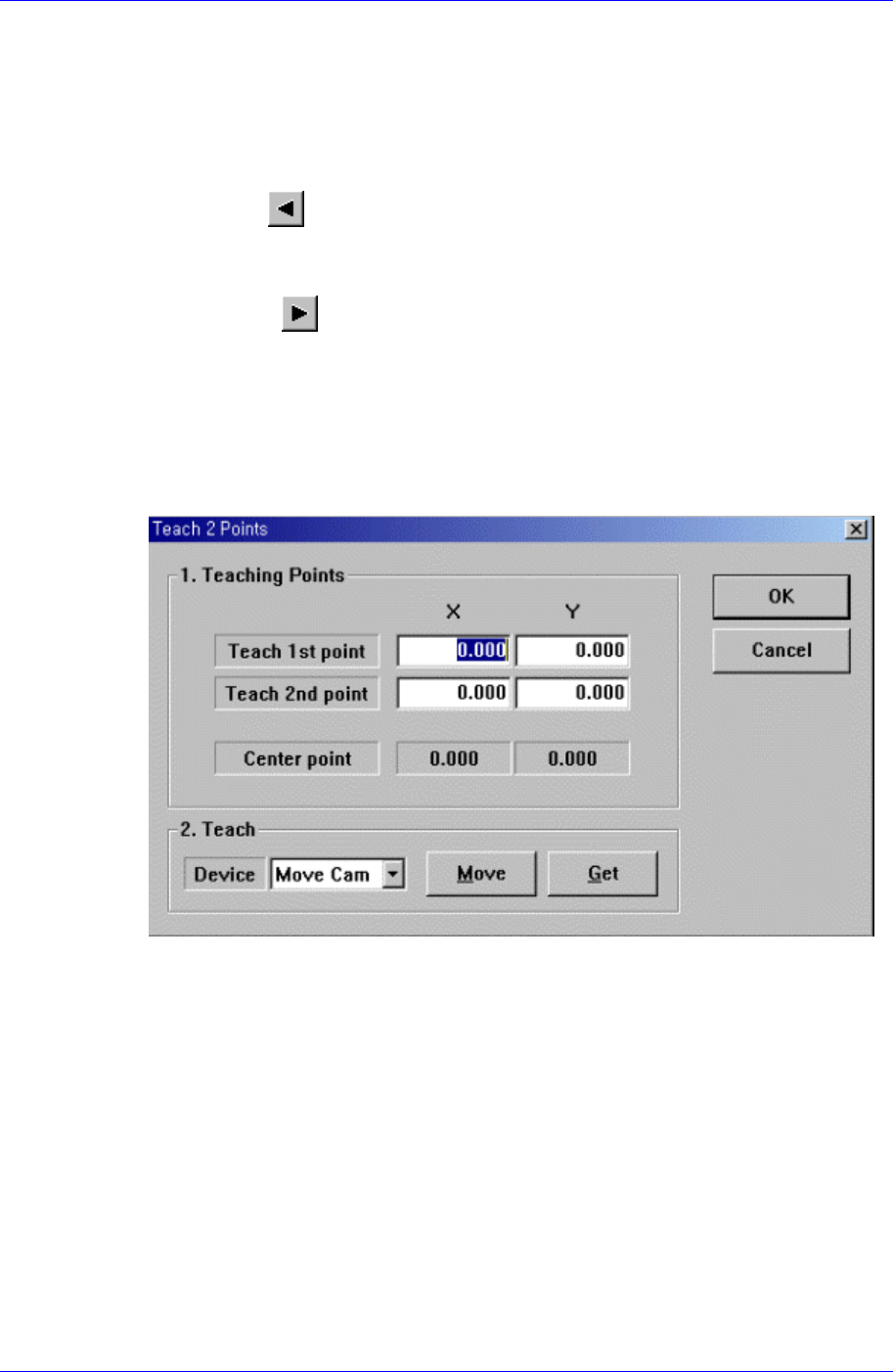
<2Pt. Teach…> button
When teaching stick feeder pickups point, the center point is calculated by teaching
two corner points at opposite angles of the pocket with the component. When this
button is clicked on, the following dialog box is displayed.
Figure 8-6. “Feeder : 2 point Teaching in the Stick Unit” dialog box
<1. Teaching Points> group
Set the positions of two corner points to find the center point.
Teach 1st point: Set the position of the first point.
Teach 2nd point: Set the position of the second point.
Center point: Finds and displays the center point from two corner points.
<2. Teach> group
Used to move the head assembly or spindle to the set position by rotating the
shafts of the X, Y-axes driving motors or to obtain the current shaft locations of
the X, Y-axes driving motors.
<Device> combo box
Used to select the corresponding device when moving the head assembly by
rotating the shafts of the X, Y-axes driving motors or to obtain the current
8-10