Administrator’s Guide(CP45FV) Eng.pdf - 第203页
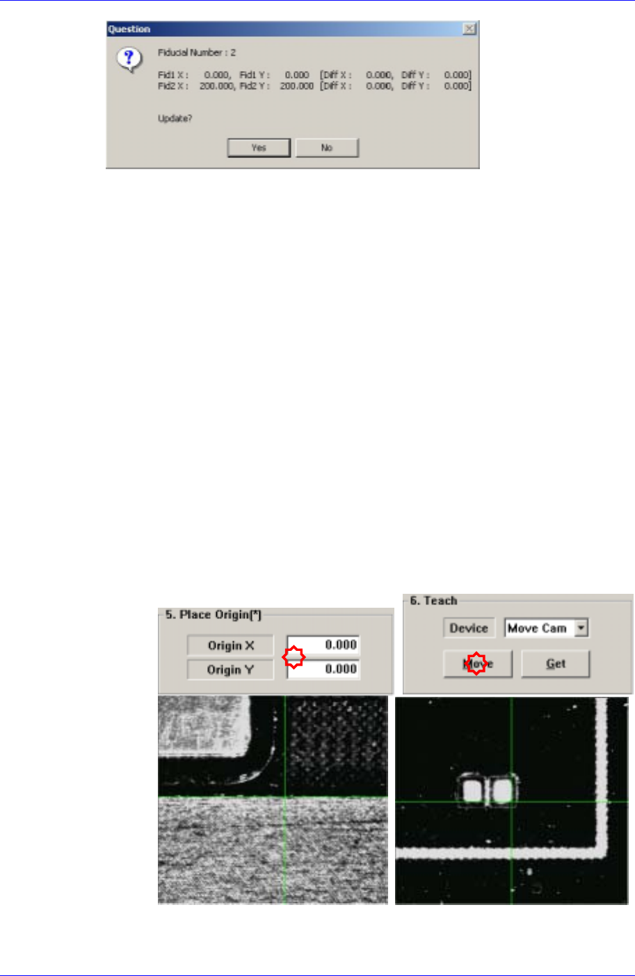
T eaching 13-7 The position of the fiducial mark displayed on the above screen is the position of the mark obtained through the scan test. If you want to update the value, click on “ Y es, ” if not click on “ No ” . This…
Samsung Component Placer CP45FV Administrator’s Guide
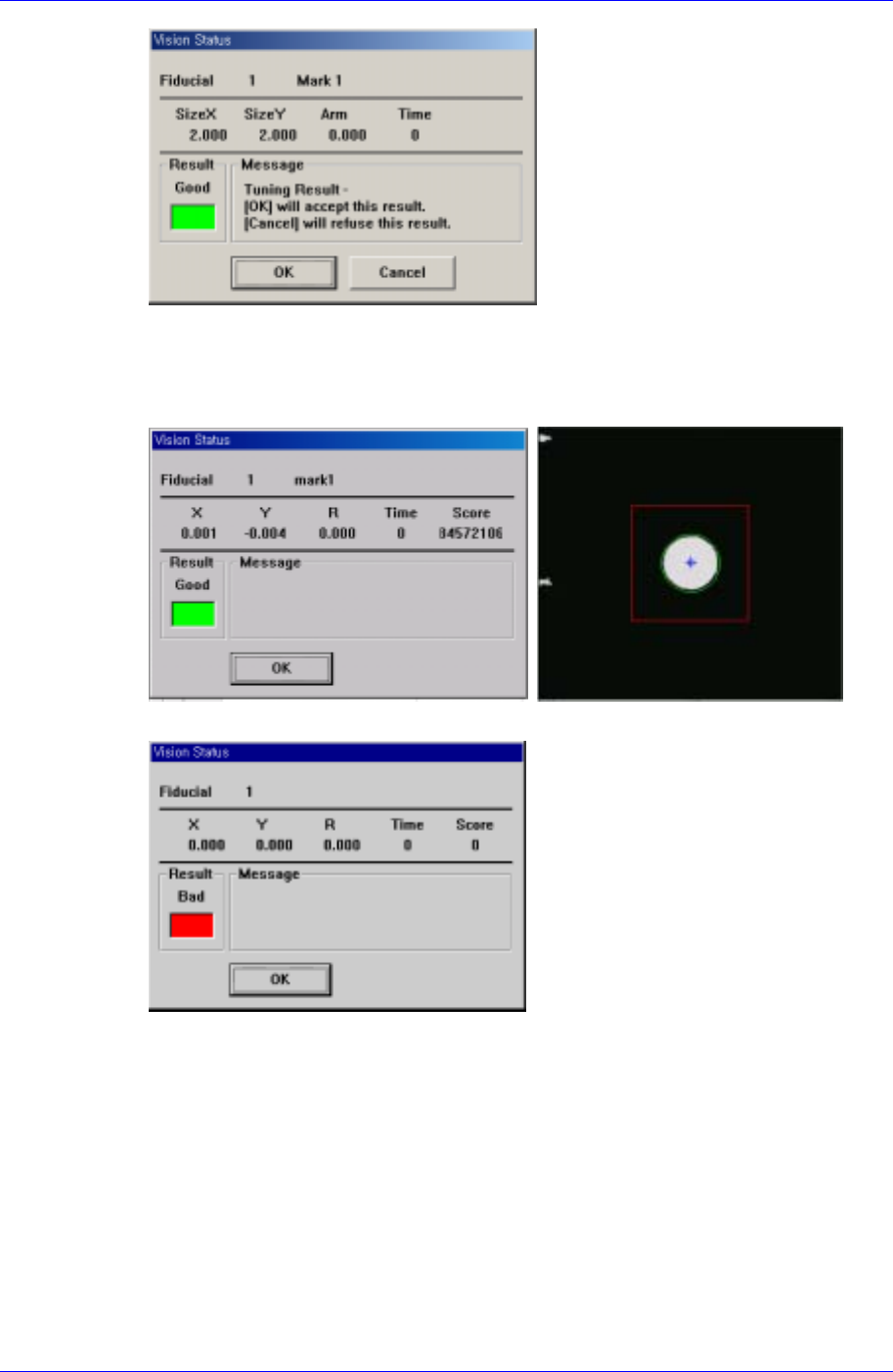
<Test> button
By using the registered mark information, tests the mark.. The accuracy of the
registered mark data can be verified. When the test is successful, the following
message box is displayed.
When the test is not successful, the following message box is displayed.
<Scan> button
Executes a scan test on the set fiducial mark. The scan test inspects the actual mark
by using the set fiducial mark position and mark data and displays the result as
follows.
13-6
Teaching
13-7
The position of the fiducial mark displayed on the above screen is the position of the
mark obtained through the scan test. If you want to update the value, click on “Yes,” if
not click on “No”. This is performed to correct the position of the mark already
entered accurately using the registered mark data. Perform more than twice for
application.
13.2. Point Teaching
13.2.1. Placement Point Teaching
This is to teach the position (center of the component) on the PCB, where the component
is to be placed. The teaching is done manually or by importing the CAD data.
Manual teaching procedure
Load the PCB to teach on the working area of the conveyor.
Enter the size of the PCB and click the <Conv.Width> button to adjust the
conveyor width to the PCB.
Feed the PCB on the convey inlet and click the <PCB In> button.
Fix the PCB and set the placement origin.
Select the fiducial camera as a teaching device and teach the position of the edge
of the component nearest to the stopper among the components to be mounted on
the PCB.
(Stopper Position Teaching) (Component Edge Position Teaching on the PCB)
Samsung Component Placer CP45FV Administrator’s Guide
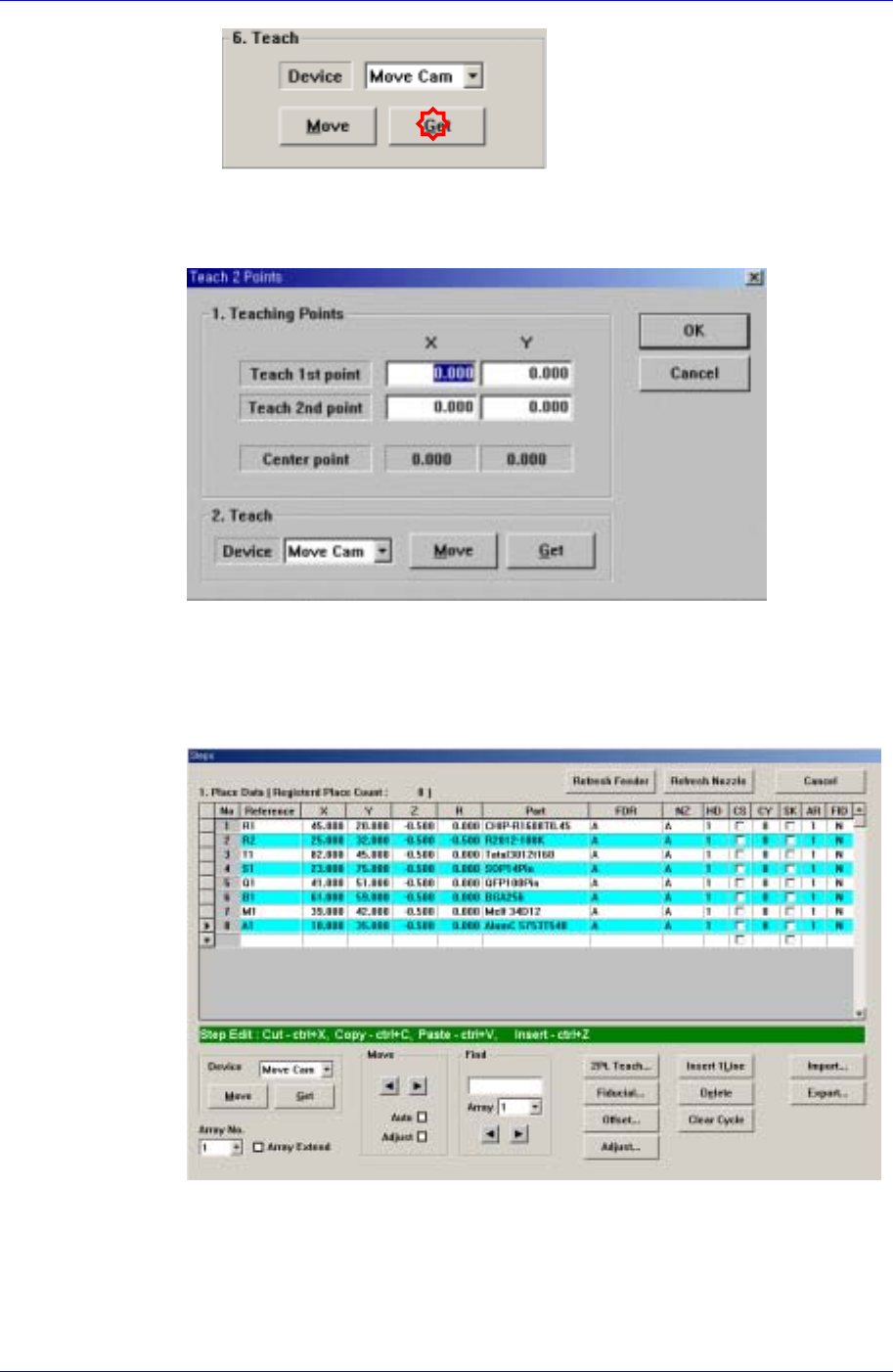
Teach the center of the component to be placed.
If possible, obtain the correct center point using the 2 point teaching method for
accurate teaching.
Teach the positions of two points on the edges facing diagonally to obtain the
center point.
Once the teaching of the two points is completed, the center of the
component is obtained automatically. Enter the coordinate as the center of
the component.
In the above dialog box, the constant value was entered as the Z value. This
allows the bottom surface of the component to be placed below the top surface of
the PCB. Sometimes the value of -0.3 ~ -0.5mm is entered in the dialog box for
accurate placement considering the PCB warping.
Placement point teaching procedure using CAD data
13-8