Administrator’s Guide(CP45FV) Eng.pdf - 第240页
Samsung Component Placer CP45FV Administrator ’ s Guide Determines whether to use a head or not. If an error occurs concerning the head, remove the selected head. However, in order to reassign the work assigned to the cu…
Machine Calibration
Chapter 15. Machine Calibration
15-1
15.1. Head [F2]
15.1.1. Head Tab dialog box
The <Head> command displays and sets the status of the head assembly. When this
button is clicked on, the following dialog box is displayed.
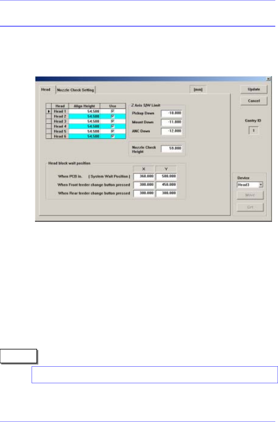
Figure 15-1. “Sys. Setup : Gantry / Head Information” dialog box
<Gantry ID> Static box
Displays the ID of the gantry to which the head assembly is attached.
<Grid> group
Set the data on the head.
<Head No> column
Displays the head number.
<Align Height> column
Set the align height.
The value “54.5” refers to the default value applied to this machine, which means
the position where the component is aligned on the top surface of the PCB.
Memo
When changing the data, the head may operate in the wrong direction since the
component alignment position is changed.
<Use> column

Samsung Component Placer CP45FV Administrator’s Guide
Determines whether to use a head or not. If an error occurs concerning the head,
remove the selected head. However, in order to reassign the work assigned to the
cute the optimizer program again.
ed the surface
of th as the base position of this limit value.
s the error message on the screen
m download.
value is "-11", which is the minimum value that can be setup during
limit for Z axis height when the Z axis is lowered for nozzle change in the
lower than 2.450 or all machines with the serial number 1188 or
e to set the height at which the nozzle is checked using a sensor is
1. n the Diagnosis menu to check the operation of the Nozzle
ck the sensor on/off state by blocking the sensor using a piece of
2. king the <PICK> button in
4. g the teaching box so that the Z-
6.
ate enabling the sensor to detect the nozzle regardless of the
7. g the teaching box so that the Z-
8. e sensor
corresponding head, exe
<Z Axis S/W Limit> group
Set the height limit for Z axis movement. when the PCB board is load
e PCB board is determined
<Pickup Down> edit box
Set the limit for Z axis height when the Z axis is lowered for component pickups.
The value "-10" refers to the setup of the Software Limit so that the component
may not be picked up at the position below -10. If an invalid value is entered, the
machine checks the set limit value and display
during operation or progra
<Mount Down> edit box
Set the limit for Z axis height when the Z axis is lowered for component pickups.
The default
placement.
<ANC Down> edit box
Set the
ANC.
<Nozzle Check Height> edit box
Set the limit for Z axis height to check component pickups by the nozzle. If there
is a change in the mechanism of the head after initial delivery from the factory,
reset the nozzle check position. The default value is 59, however, it may vary
depending on the machine. This is applied to all machines with the MMI
version
lower.
The procedur
as follows;
Select the I/O i
Check Sensor.
※ Check the sensor operation while turning on or off the sensor
※ Che
paper.
Mount the TN04 nozzle on the HEAD 3 by clic
the ANC dialog box with manual manipulation.
3. Select the View menu and then select the Current Position.
Move down the spindle of the HEAD 3 usin
axis height of the HEAD 3 becomes 60mm.
5. Set the Amp switch of the sensor to Set mode.
Turn on the Amp switch of the sensor since at this height (60mm) the sensor
is in the ON st
nozzle height.
Move down the spindle of the HEAD 3 usin
axis height of the HEAD 3 becomes 50mm.
Turn off the Amp switch of the sensor since at this height (50mm) th
15-2
Machine Calibration
15-3
shall switch to off state natually even though the nozzle is mounted.
10.
d, move up the
ge
※ S d red LEDs turn on
f the spindle of the HEAD 3 is moved down, only the green LED
D turns off or the red LED turns on, repeat the
11.
ion has been done normally. Otherwise, repeat the above
procedure.
9. Then set the Amp switch of the sensor to Run mode.
Increase the Z-axis height of the HEAD 3 by 1.0mm increments from 50mm
to 55.0mm using the teaching box. If the detection state remains unchanged
even when the Z-axis height of the HEAD 3 is increase
spindle of the HEAD 3 until Z-axis height reaches 57mm.
If the green and red LEDs turn on simultaneously between the height ran
of 57.0 ~ 58.0mm, it signifies that the calibration has been done normally.
et the Z-axis height where the green an
simultaneously as the Nozzle Check Height.
However, i
turns on.
But at this time if the green LE
above procedure from step 4.
In order to check the operation of the sensor, select any ANC hole from the
ANC dialog box using any head, and then click the <PICK> button. If the
error message “THE HEAD HAS NO NOZZLE” is displayed on the screen,
the calibrat
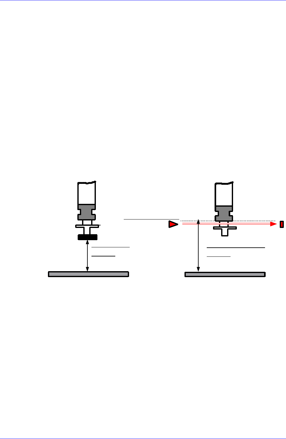
ALIGN HEIGHT
=54.5mm
PCB
NOZZLE CHECK HEIGHT
=59.0mm
NOZZLE CHECK SNESOR
PCB
Set the waiting position for the head assembly.
ystem, move the head to the coordinate set
kup position of the feeder supplying the
d assembly.
n panel of the machine
<Head Assembly wait position> group
<When PCB in> edit box
Set the waiting position for the head assembly when the PCB is being loaded.
In case the Wait Type is selected as S
here and wait when loading the PCB.
In case the Wait Type is selected as Auto, if there is a fiducial mark, the head
waits at the fiducial mark position when loading the PCB. If there is no fiducial
mark, the head waits at the pic
component to be placed first of all.
<When Front feeder change button pressed> edit box
When the “Front feeder change” button on the front operation panel of the
machine is pressed, set the waiting position for the hea
<When Rear feeder change button pressed> edit box
When the “Rear feeder change” button on the rear operatio