Administrator’s Guide(CP45FV) Eng.pdf - 第153页
S tep Pr ogramming Chapter 9. S tep Programming 9-1 9.1. Step-Program The <Step> command edits data on PCB placement points, component fiduci al marks, components to be placed, component supplying feeders, and nozz…

Samsung Component Placer CP45FV Series Administrator’s Guide
<Current Pocket> group
<X>: Set the pocket number of the tray to move to or pick up from in X direction.
<Y>: Set the pocket number of the tray to move to or pick up from in Y direction.
<Pallet Out> button
Release the pallet to be finished placement from the elevator of the tray feeder.
<Pallet In> button
Loads the pallet to be ready for placement from the elevator of the tray feeder.
<Device> combo box
Selects the corresponding device to move the head assembly by rotating the driving
shafts of the X, Y-axes motors, move or rotate the spindle or obtain the current
coordinate of the device to be selected. Available devices are as follows;
Move Cam: Selects Teaching Camera.
Head1: Selects Head1.
Head2: Selects Head2.
Head3: Selects Head3.
Head4: Selects Head4.
Head5: Selects Head 5.
Head6: Selects Head6.
Beam: Selects Beam.
<Move> button
Moves the head assembly by rotating the shafts of the X, Y-axes driving motors using
the device selected from the <Device> combo box. Before executing “Move”, the cell
in the grid corresponding to the desired position must be clicked on with a mouse.
<Get> button:
Reads in the current position of the XY axis of the device selected in <Device>.
Before executing “Get”, the cell in the grid corresponding to the position to be read
must be clicked on.
<Install to Feeder Base> group
Displays the feeder base unit and slot number when the tray unit is set to the feeder
base.
<Feeder Base>
Displays the feeder base on which the corresponding tray unit is installed
currently. The numbers displayed are as follows.
0: Not installed on any feeder base.
1: Installed on Feeder Base1(Front Feeder Base).
2: Installed on Feeder Base2(Rear Feeder Base).
<Slot No.>
Displays the number of the feeder base slot in which the corresponding tray unit
is installed currently. The numbers displayed are as follows.
0: Not installed in any slot.
1 - 52: Installed in the corresponding number slot.
8-20
Step Programming
Chapter 9. Step Programming
9-1
9.1. Step-Program
The <Step> command edits data on PCB placement points, component fiducial marks,
components to be placed, component supplying feeders, and nozzles to pick up
components. When this command is executed, the following initial screen is displayed.
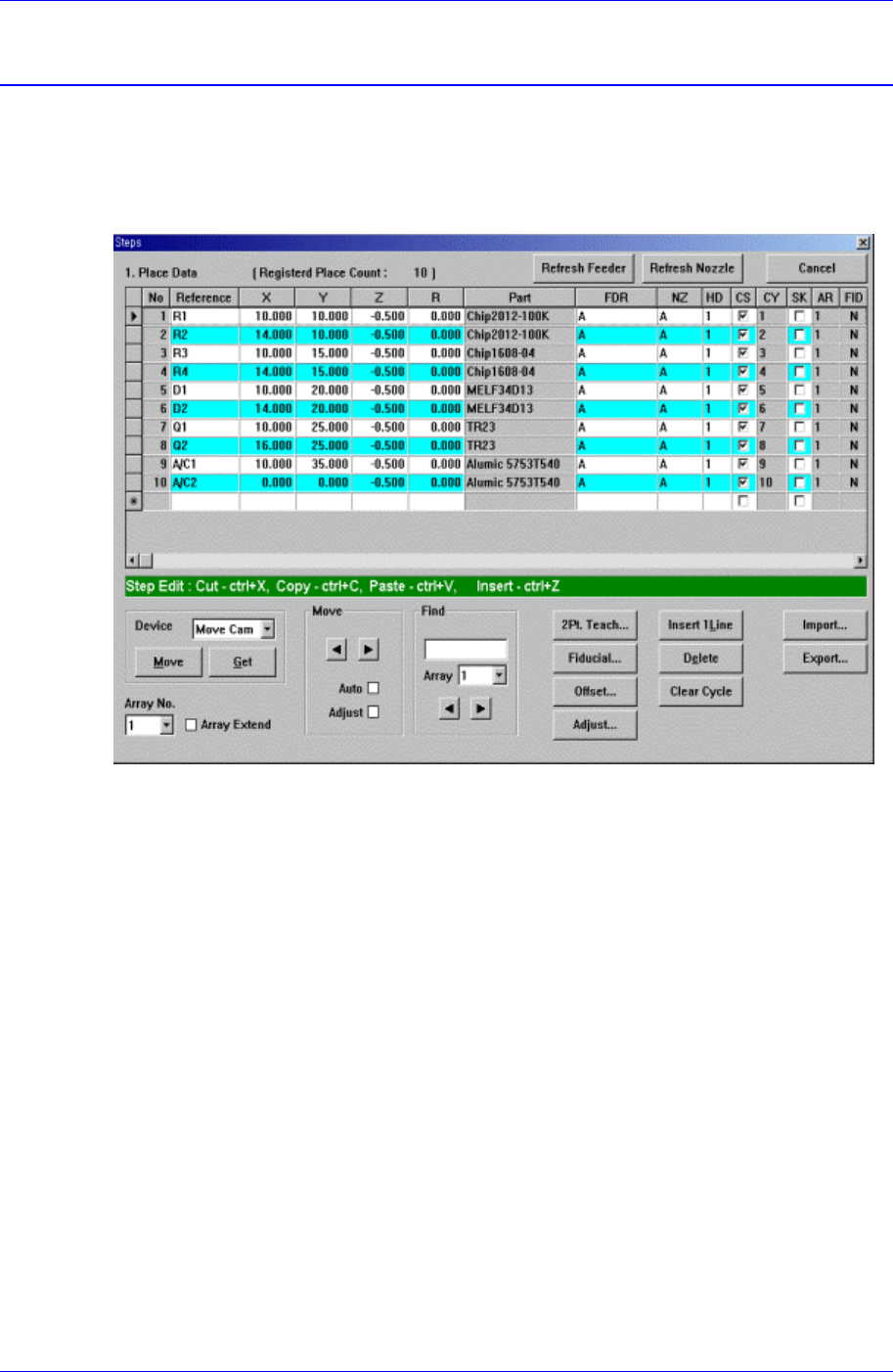
Figure 9-1 “Steps” Dialog box (Initial screen without placement point)
<1. Place Data> group
Set the edit data related to placement.
<Reference> column
Set the reference name of the placement point. In general, enter the value of R1,
R2, C1, and C2 on the PCB(up to 8 characters)
<X> column
Set the X position of the placement point.
<Y> column
Set the Y position of the placement point.
<Z> column
Set the Z position of the placement point.
<R> column
Set the R position(rotation angle of the placement component) of the placement
position.
<Part> column
Select the component to place.
<FDR> column

Samsung Component Placer CP45FV Series Administrator’s Guide
Select the feeder to supply the component.
<NZ> column
Select the nozzle to pick up the component.
<HD> column
Select the head to pick up the component.
<CS> column
When you want to start a new cycle, check this check box.
<CY> column
When <Cycle> is clicked on, the corresponding cycle number is displayed.
<SK> column
Check the check box when you want to skip the placement point.
<AR> column
Select the array PCB number to which the placement point belongs.
<FID> column
If the fiducial mark data of the placement point has been set in <Fiducial…>, “Y”
is displayed, if not “N” is displayed.
<Device> combo box
Selects the corresponding device to move the head assembly by rotating the driving
shafts of the X, Y, Z and R-axes motors, move or rotate the spindle or obtain the
current coordinate of the device to be selected. Available devices are as follows;
Move Cam: Selects Teaching Camera.
Head1: Selects Head1.
Head2: Selects Head2.
Head3: Selects Head3.
Head4: Selects Head 4.
Head5: Selects Head5.
Head6: Selects Head6.
Beam: Selects Beam.
<Move> button
Moves the head assembly by rotating the shafts of the X, Y, Z and R-axes driving
motors using the device selected from the <Device> combo box. At this time, the cell
in the grid corresponding to the desired position must be clicked on with a mouse.
<Get> button
Reads in the current position of XY, Z, and R axes of the device selected in <Device>.
At this time, the cell in the grid corresponding to the desired position must be clicked
on first with a mouse.
<Array No.> combo box
Displayed only in the case of Array PCB.
Select the array PCB number to move.
<Array Extend> check box
Displayed only in the case of Array PCB.
Expand the placement point to one PCB by using the offset value of array PCB.
9-2