Administrator’s Guide(CP45FV) Eng.pdf - 第158页
Samsung Component Placer CP45FV Series Administrator ’ s Guide <Position T ype> combo box Select the number of fiducial marks. Available nu mbers of fiducial marks are as follows. None: No fiducial mark. 1 Part: …

Step Programming
9-5
shafts of the X, Y-axes driving motors or to obtain the current shaft locations of
the X, Y-axes driving motors.
<Device> combo box
Used to select the corresponding device when moving the head assembly by
rotating the shafts of the X, Y-axes driving motors or to obtain the current
coordinate of the device to be selected. Available devices are as follows;
Move Cam: Selects Teaching Camera.
Head1: Selects Head1.
Head2: Selects Head2.
Head3: Selects Head3.
Head4: Selects Head4.
Head5: Selects Head5.
Head6: Selects Head6.
Beam: Selects Beam.
<Move> button
Moves the head assembly by rotating the shafts of the X, Y-axes driving motors
using the device selected from the <Device> combo box. Before executing
“Move”, the edit box corresponding to the desired position must be clicked on
with a mouse.
<Get> button
Reads in the current position of the XY axis of the device selected in <Device>.
Before executing “Get”, the edit box corresponding to the desired position must
be clicked on with a mouse.
<OK> button
Sets the obtained center point as the new pickups point and closes the dialog box.
<Cancel> button
Ignores the obtained center point and closes the dialog box.
<Fiducial…> button
If the placement point has a fiducial mark, sets the fiducial mark data. When this
button is clicked on, the following dialog box is displayed.
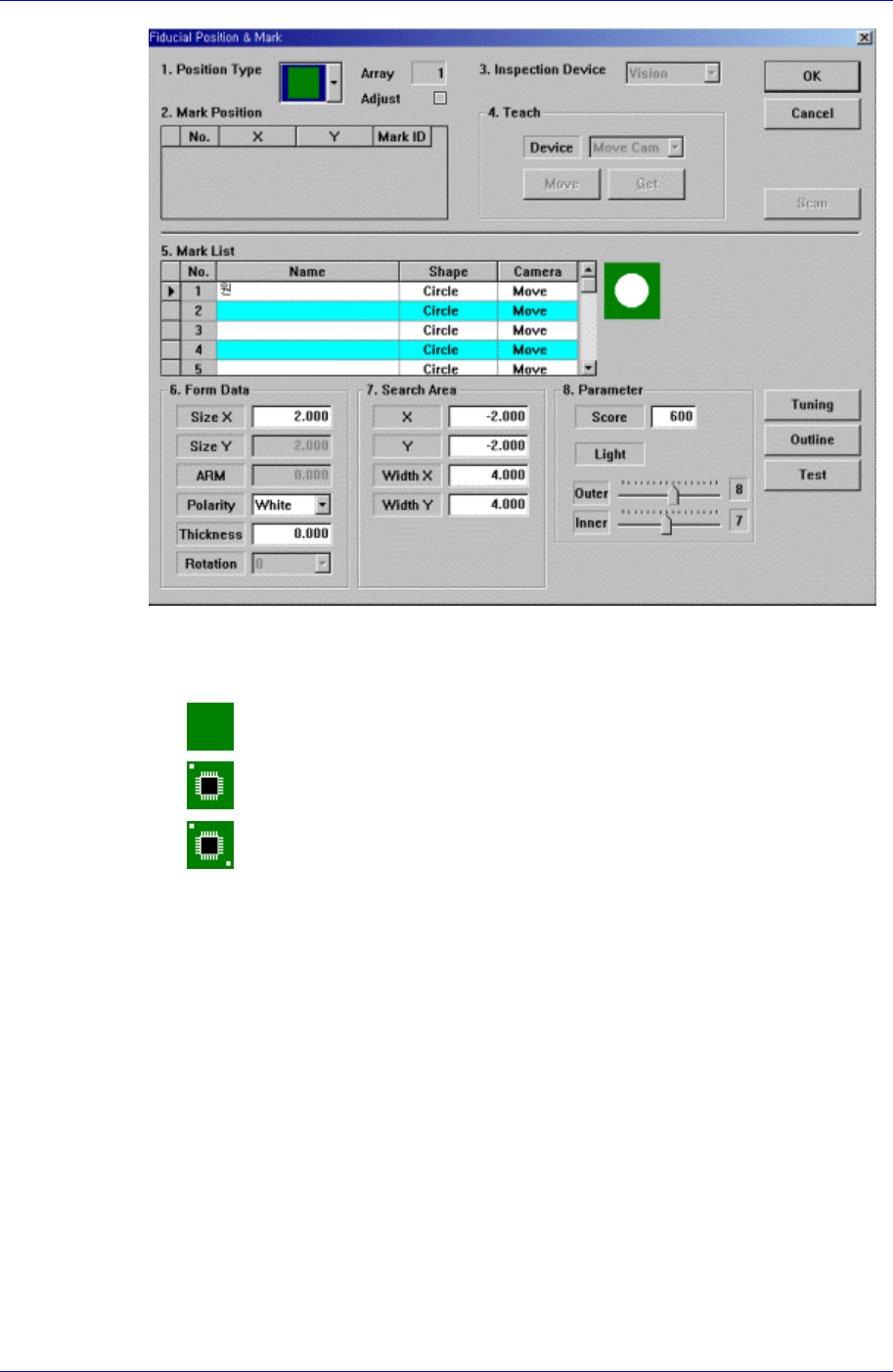
Samsung Component Placer CP45FV Series Administrator’s Guide
<Position Type> combo box
Select the number of fiducial marks. Available numbers of fiducial marks are as
follows.
None: No fiducial mark.
1 Part: 1 fiducial mark for placement point adjustment.
2 Part: 2 fiducial marks for placement point adjustment.
For the rest, please refer to the explanation of the <Fiducial Mark…> button in
<11.1 Board>.
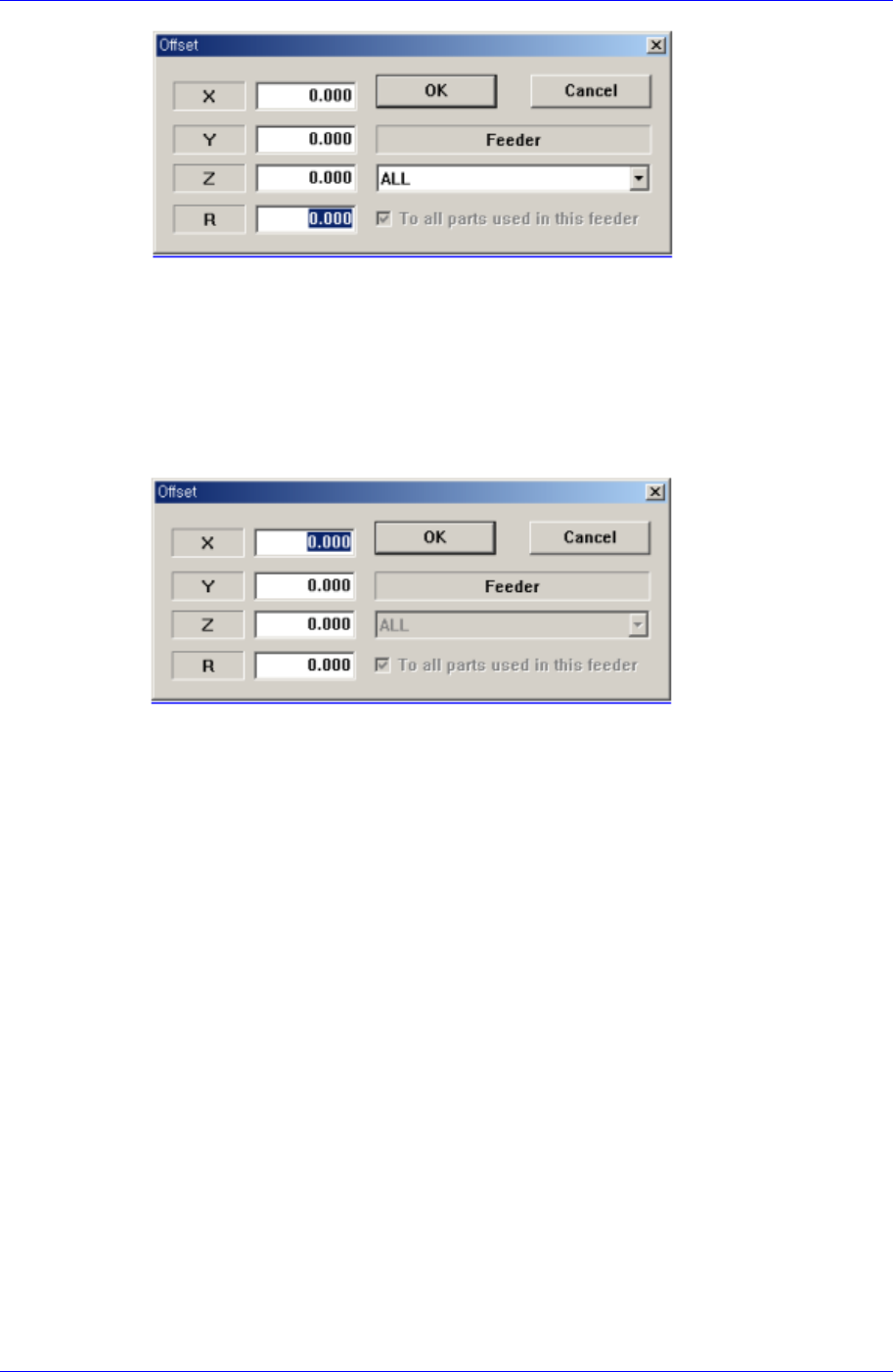
<Offset…> button
Adds the offset value to the position of placement point. Before executing this
function, X column or Y column or Z column or R column or the line to add the
offset value must be selected in the grid. When this button is clicked on, the following
dialog box is displayed.
9-6
Step Programming
9-7
<The case to select a column>
The case to select a column
If the Feeder item is selected as ‘All’, it will be applicable to all steps.
In case a particular feeder is selected as the Feeder item, the offset value will be
applicable only for the step that uses the particular feeder. However, in case “To
all parts used in this feeder” is set, the offset value is applied to all the steps that
have the part names identical with the ones of the feeder being selected currently.
<The case to select a line>
<X> edit box
Set the X offset value.
<Y> edit box
Set the Y offset value.
<Z> edit box
Set the Z offset value.
<R> edit box
Set the R offset value.
<OK> button
Closes the dialog box and adds the set offset value to the selected line in the grid.
<Cancel> button
Ignores the set offset value and closes the dialog box
<Adjust…> button
It is a function used to change the PCB step coordinate or to check and adjust the gap
between the previous fiducial mark coordinate and the current fiducial mark
coordinate to use the previous step coordinate when the backup table is down
accidentally.
<Insert 1Line> button
Inserts a new placement point before the currently selected line in the grid.