Administrator’s Guide(CP45FV) Eng.pdf - 第178页
在线预览 Administrator’s Guide(CP45FV) Eng.pdf PDF 文档。

Optimization
10-11
xS: Component pickup by x heads simultaneously
<Cycle> group
The status of component allocation, feeder allocation, and nozzle allocation in the
final step program is displayed in this group. Three radio buttons on the bottom let
the user to select one and see the allocation status. The number in the rightmost
column displays the number of cycle repetitions.
Component
In the component allocation status, the component to be operated by each head is
displayed with cx, x is the number given to a component. (Component name is
not displayed here)
Feeder
In the feeder allocation status, the feeder lane from which the head picks up is
displayed. The front feeder base is indicated by Fx, and the rear feeder base by
Rx. Here x is the feeder lane number. And, the stick feeder is indicated by Sx,
and tray feeder by Tx, here x is not a feeder unit name but a division by pickup
point
Nozzle
The nozzle allocation status shows which nozzle is used for which head. The
name of the nozzle to be used by each head is displayed.
Production Setup
Chapter 11. Production Setup
11-1
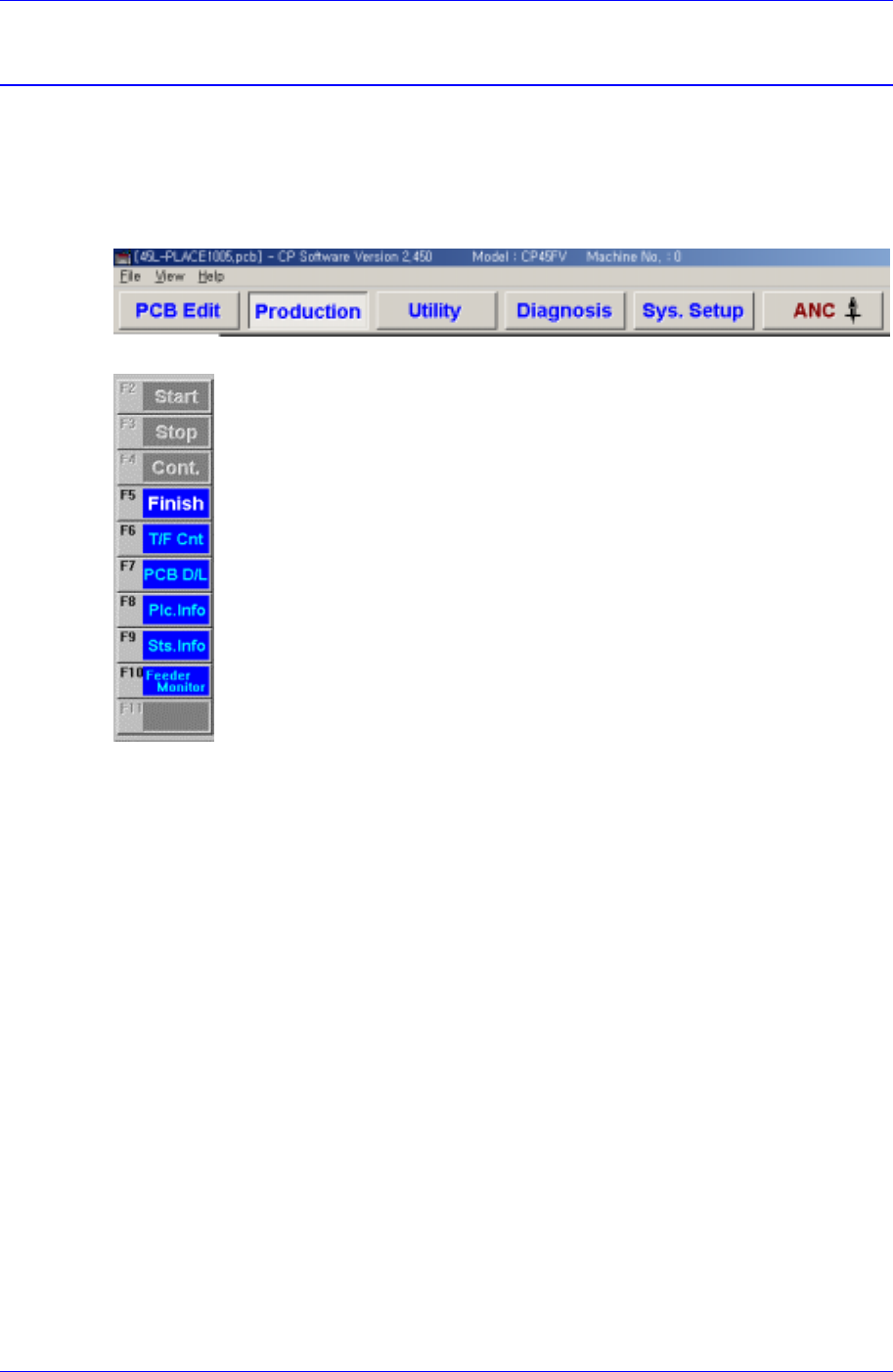
The production menu is composed of nine submenus; Start, Stop, Cont., Finish, T/F Cnt,
PCB D/L, Plc. Info, Sts. Info and Feeder Monitor.
This menu performs the function of monitoring PCB (Printed Circuit Board) placement
operation..
Figure 11-1. When the Production command is selected
Figure 11-2. Submenus of the Production command(Initial status)
11.1. Production Main
When the production button is clicked on, the following screen is displayed.