Administrator’s Guide(CP45FV) Eng.pdf - 第94页
Samsung Component Placer CP45FV Series Administrator ’ s Guide Fix3 Cam: Fix Camera3. (If Fix Cam era3 is installed) Head1 Cam: Fly Camera for Head1. Head2 Cam: Fly Camera for Head2. Head3 Cam: Fly Camera for Head3. Head…
Part Registration
7-9
7.2. CHIP component data setting
7.2.1. CHIP-Circle component data setting
Set the align data for circular CHIP components.
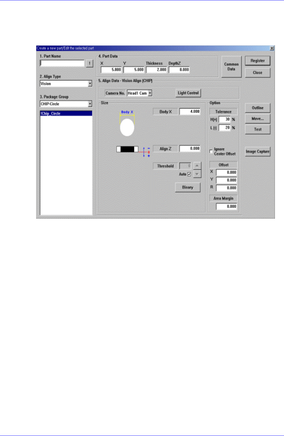
Figure 7-7. “Align Type = Vision,, Package Group = CHIP-Circle” dialog box
<Size> group
Set the align size.
<Body X> edit box
Set the diameter of component.
<Outline> button
Displays the outline of the component on the vision monitor by using the set align
data.
<Repeat…> button
Performs the component recognition test repeatedly. It is not explained here since it is
for debugging.
<Close> button
Ignores the set data and closes the dialog box.
7.2.1.1. Common Align Data
The following items are common to CHIP component.
<Camera No.> combo box
Select the camera to recognize the component. Available cameras are as follows.
Fix1 Cam: Fix Camera1. (If Fix Camera1 is installed)
Fix2 Cam: Fix Camera2. (If Fix Camera2 is installed)
Samsung Component Placer CP45FV Series Administrator’s Guide
Fix3 Cam: Fix Camera3. (If Fix Camera3 is installed)
Head1 Cam: Fly Camera for Head1.
Head2 Cam: Fly Camera for Head2.
Head3 Cam: Fly Camera for Head3.
Head4 Cam: Fly Camera for Head4.
Head5 Cam: Fly Camera for Head5.
Head6 Cam: Fly Camera for Head6.
<Light Control> button
Sets the lighting for the camera to recognize the component. When this button is
clicked on, the following dialog box is displayed.
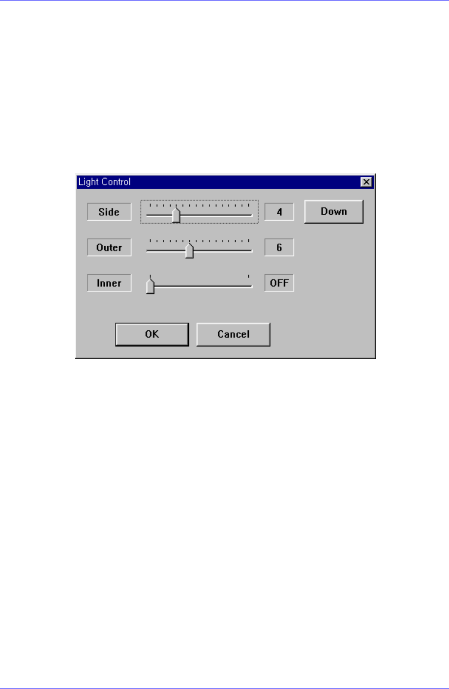
Figure 7-8 “Camera No. = Head Camera “ dialog box
<Side>
Set a value for the side light. (0 – 15)
<Down> button
Moves down the side light.
<Outer>
Set a value for the outer light. (0 - 15)
<Inner>
Set a value for the inner light. (ON, OFF)
<OK> button
Saves the set light value and closes the dialog box.
<Cancel> button
Closes the dialog box without saving the set light value.
7-10
Part Registration
7-11
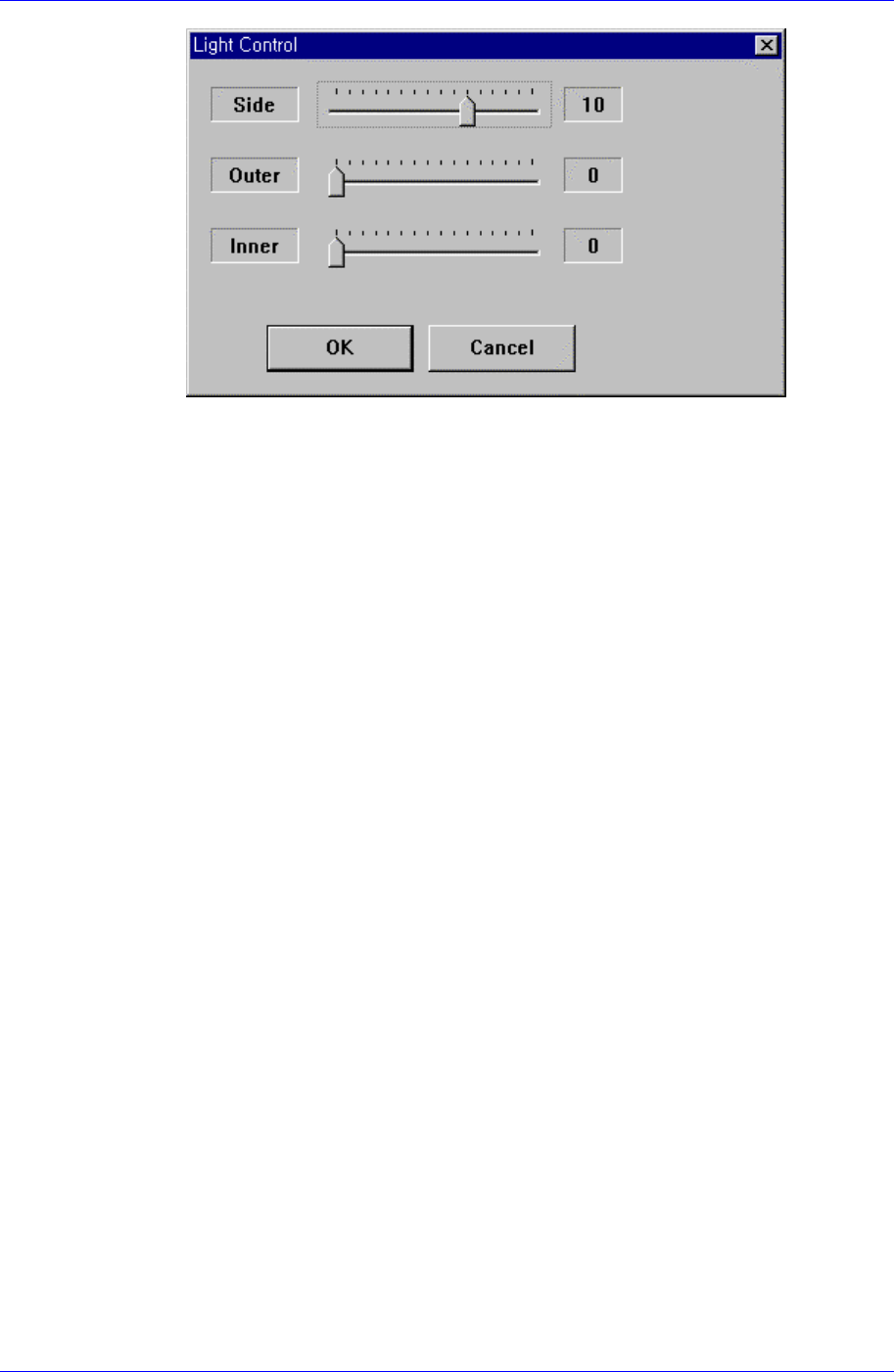
Figure 7-9. “Camera No. = Fix Camera “ dialog box
<Side>
Set a value for the side light. (0 – 15)
<Outer>
Set a value for the outer light. (0 - 15)
<Inner>
Set a value for the inner light. (0 - 15)
<OK> button
Saves the set light value and closes the dialog box.
<Cancel> button
Closes the dialog box without saving the set light value.
<Align Z> edit box
Set the height for recognition. Based on the component surface, if the top is to be
recognized, set - value and if the bottom is to be recognized, set + value.
<Threshold> edit box
When there is a pre-treatment process for component recognition and the gray
level image is converted into binary(binary mode), it is the value used as the
criteria to determine black and white.
The value range is 0 – 255(0: black, 255: white), and this value serves to
differentiate the component from the background. When the set value is 0, the
value is set automatically during component recognition.
For example, if the <Threshold> value is 100, all the values under 100 in the
vision image are recognized as black, and all the values over 100 are recognized
as white.
<Auto> check box
Check this box to set the <Threshold> value automatically.
<Binary> button
Displays the binary image of the component on the Vision Monitor screen.
<Option> group
Set the Align Option data.