Administrator’s Guide(CP45FV) Eng.pdf - 第264页
Samsung Component Placer CP45FV Administrator ’ s Guide 4. Then adjust the lighting of the fi xed camera so that the plate hole center can be seen clearly . Then align th e plate hole center with the fixed camera center …
Machine Calibration
15-25
camera calibration.
8. If the message, “Calibration is prepared. To Calibrate, Click [Next].” is
displayed, click the <Next> button. Then the calibration begins. At this
time the machine locates the center of the black circle at the bottom of
the nozzle mounted on the Head1 through the fixed camera, recognizes
the position and calculates the distance moved.
9. Once the calibration is completed, the calibration value is displayed.
10. Perform the calibration for the heads from the Head2 to Head6 in the
same manner according to the message.
11. Once the above procedure is completed, click the <Update> button and
apply the changed value. Then the head offset information displayed in
the Head Device Offset dialog box is updated automatically.
<Move Cam Offset> button
Calibrates the offset of the move camera (fiducial camera). To perform this
procedure, the Move Camera Calibration Plate is needed.
The move camera offset calibration procedure is as follows;
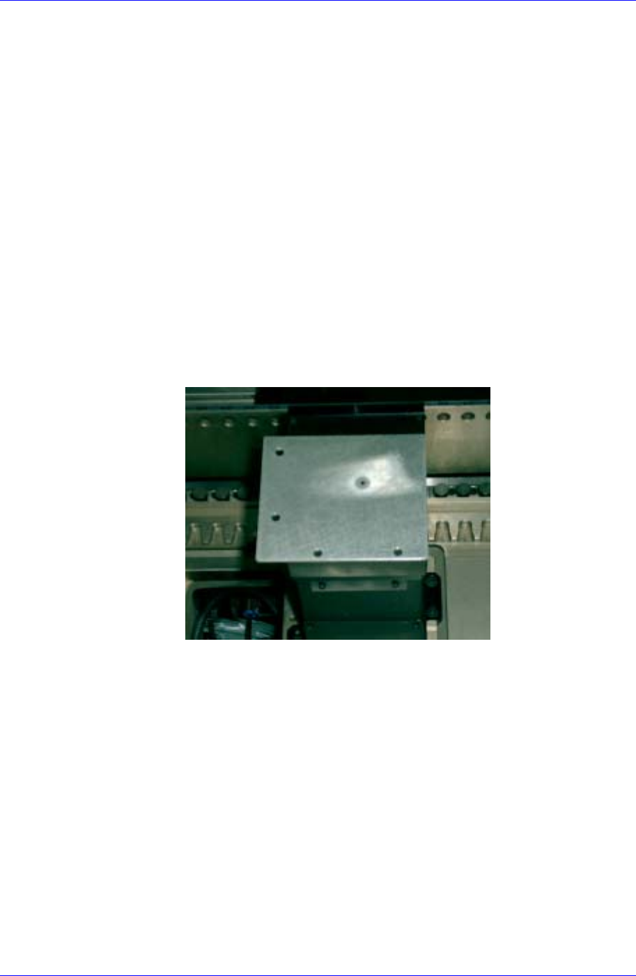
1. Install the Move Camera Calibration Plate so that it covers the upper
surface of the fixed camera referring to the figure shown below.
A guide is attached on both sides of the calibration plate. If the guide is
set so that it is installed near the camera, the hole center falls on the
camera center.
2. Click the <Move Cam. Offset> button in the <Menu> group of the Auto
Calibration dialog box.
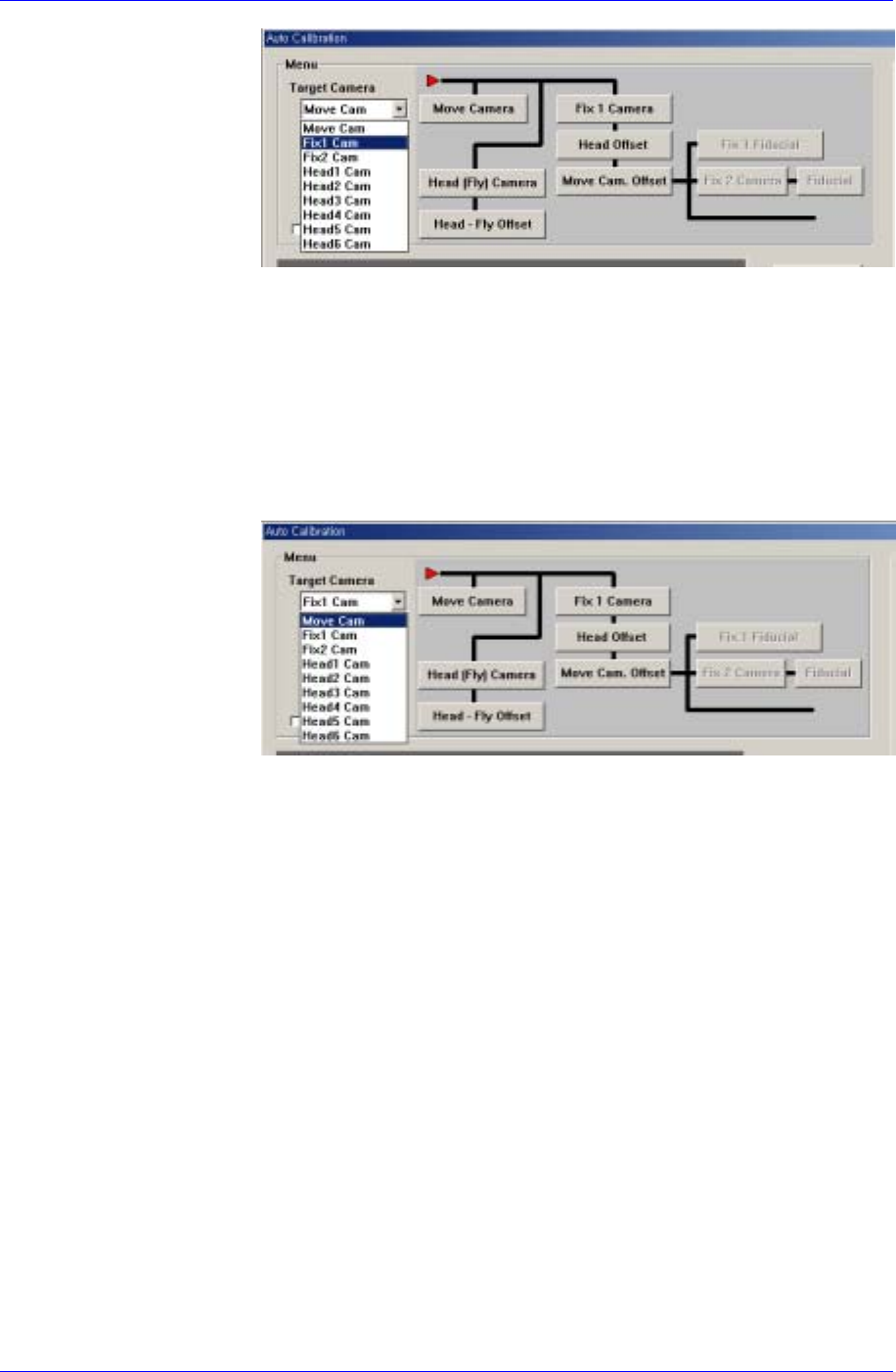
3. If the message, “Put a tool sheet on Upward (Fix) Camera 1, and adjust
tool center. If finish, Click [Next]” is displayed, select the “Fix1 Cam” in
the <Target Camera> combo box.
Samsung Component Placer CP45FV Administrator’s Guide
4. Then adjust the lighting of the fixed camera so that the plate hole center
can be seen clearly. Then align the plate hole center with the fixed
camera center (cross hair center), and click the <Next> button.
5. If the message, “Move to center position of [Fix 1] camera. To move,
Click [Next].” is displayed, align the cross hair center of the Move
Camera (Fiducial Camera) with the plate hole center using the teaching
box. Then click the <Next> button.
6. If the message, “1. First, Select Move Camera and adjust light …” is
displayed, select the “Move Cam” in the <Target Camera> combo box.
7. And, select the Move Camera to adjust the lighting in the same manner
so that the plate hole center can be seen clearly. Then align the cross hair
center of the Move Camera with the center of the plate hole and click the
<Next> button.
8. When the calibration is completed, click the <Update> button to apply
the changed value.
<Mark Dia (Sheet)> edit box
Set the diameter of the calibration tool for the move camera.
<Tool Mark Dia> edit box
Set the diameter of the calibration tool for the fix camera.
<Tool Height> edit box
Set the length of the calibration tool.
<White Mark> check box
In the case of white mark, check it..
<Score> edit box
Set the recognition value to recognize the calibration tool.
<Move Length Head Cam> edit box
Set the distance to move the calibration tool for the move camera.
<Move Length Fix Cam> edit box
15-26

Machine Calibration
15-27
Set the distance to move the calibration tool for the fix camera.
<BUT Up/Down> button
Moves up/down the BUT(Back Up Table).
<Download cam. info> button
Downloads the camera data to the machine.
<Move to home pos.> button
Moves the device selected in <Device> to Home.
<Mirror open / close> button
Opens or closes the mirror .
<Device> combo box
Selects the corresponding device to move the head assembly by rotating the
driving shafts of the X, Y and Z-axes motors, move or rotate the spindle or obtain
the current coordinate of the device to be selected. Available devices are as
follows;
Move Cam: Selects Teaching Camera.
Head1: Selects Head1.
Head2: Selects Head2.
Head3: Selects Head3.
Head4: Selects Head4.
Head5: Selects Head5.
Head6: Selects Head6.
Beam: Selects Beam.
<Move to fix 1 Cam.> button
Moves the device selected in the Device to the position of the fix camera.
<Z axis Up/Down> button
Lowers the Z axis of the head selected in the Device.
<No real motion> check box
Determines whether to really execute the nozzle pick/put motion or to manipulate
the data only. When it is checked, only the data is manipulated.
<Put all nozzle> button
Puts all nozzles in the head.
<Put> button
Puts the nozzle in the head selected in the Device.
<Pick> button
Picks the calibration tool with the head selected in the Device.
<Update> button
Saves the set data and closes the screen.
<Cancel> button
Ignores the set data and closes the screen.