Administrator’s Guide(CP45FV) Eng.pdf - 第98页
Samsung Component Placer CP45FV Series Administrator ’ s Guide mirror and sets the light. If the <Camera No.> to be aligned is the fix camera, moves the Z axis of the head to a safe height, m oves the head block to…
Part Registration
7-13
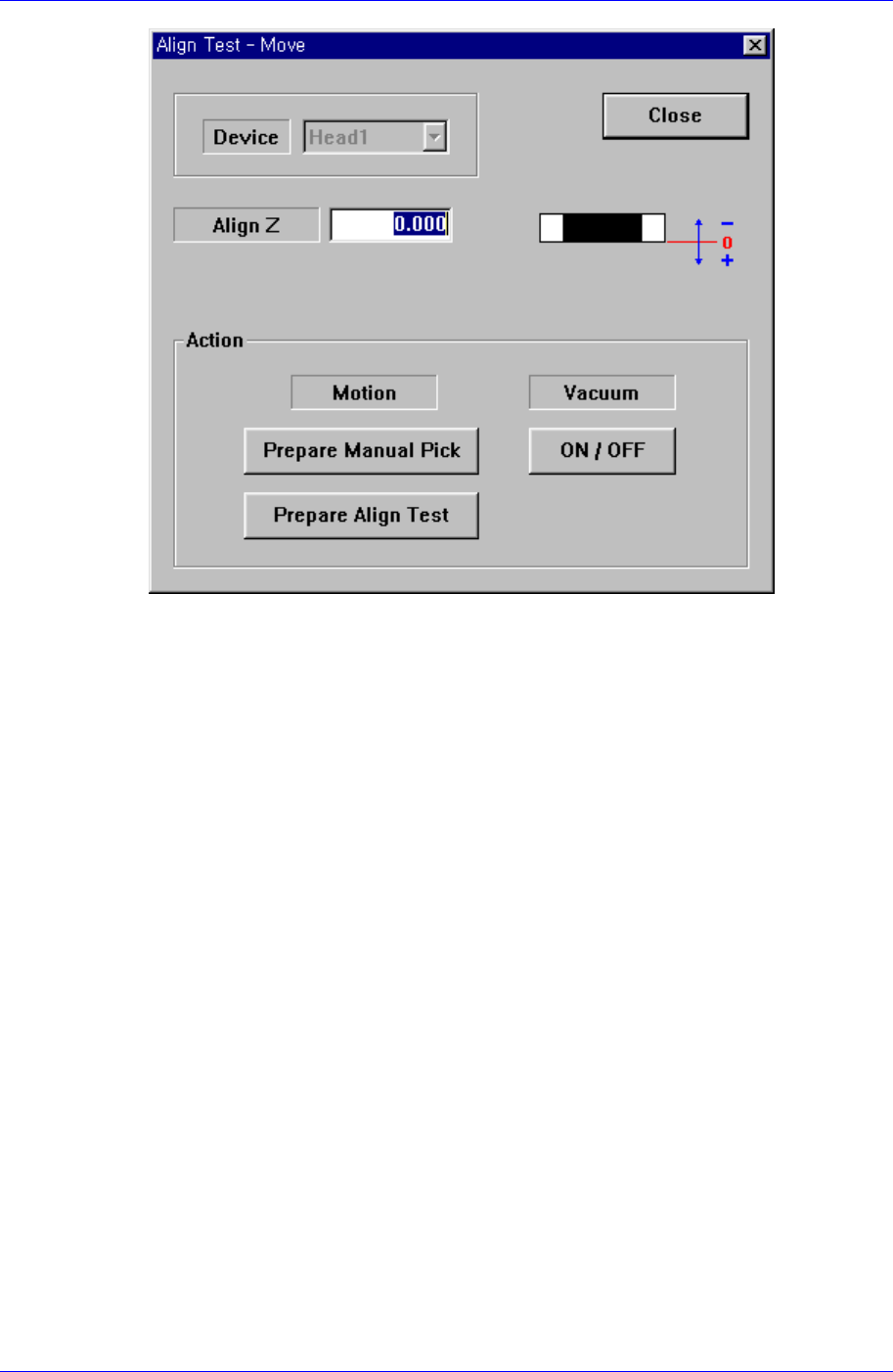
<Device> combo box
Selects the corresponding device to move the head assembly by rotating the
driving shafts of the X and Y motors or obtains the current coordinate of the
device to be selected. Applicable devices are as follows;
Move Cam: Selects the Teaching Camera.
Head1: Selects Head1.
Head2: Selects Head2.
Head3: Selects Head3.
Head4: Selects Head4.
Head5: Selects Head5.
Head6: Selects Head6.
Beam: Selects Beam.
When the <Camera No> has been set to the head camera in component align data,
the <Device> combo box is inactivated.
<Align Z> edit box
Set the height for recognition. Based on the component surface, if the top is to be
recognized, set - value, and if the bottom is to be recognized, set + value.
<Action> group
<Prepare Manual Pick> button
Moves the head block to the pickups point when the component is to be
adsorbed to the head manually. Moves to the Home position of the machine.
<Prepare Align Test> button
Prepares for the component align test. If the <Camera No.> to be aligned is
the fly camera, moves the Z axis of the head to the align height, closes the
Samsung Component Placer CP45FV Series Administrator’s Guide
mirror and sets the light. If the <Camera No.> to be aligned is the fix camera,
moves the Z axis of the head to a safe height, moves the head block to the fix
camera position, and then moves the Z axis of the head to the align height.
<Vacuum ON/OFF> button
Turns on/off the vacuum generator of the head for component pickups or
release.
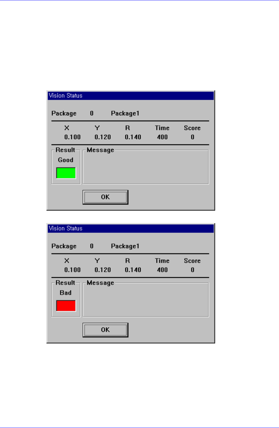
<Test> button
Tests component recognition by using the set align data. When the test is successful,
the following message box is displayed.
When the test is not successful, the following message box is displayed.
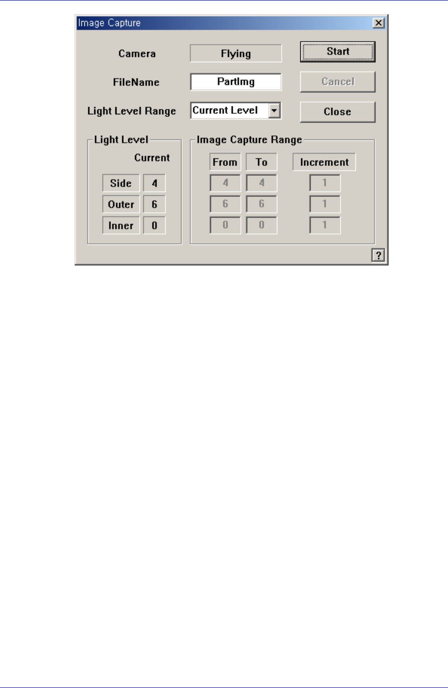
<Image Capture> button
Helps to specify the optimum lighting value. The lighting is gradually changed
automatically and the images are saved. The user can check the best image and
identify the optimum lighting value.
7-14
Part Registration
7-15
Figure 7-10. “Image Capture” dialog box
<Camera> caption box
Displays the camera to be used for image capture.
<Filename> edit box
Enters the filename to be used for image saving.
<Light Level Range> combo box
Selects the light level for each light and basic setup range.
Rough
Saves the image by increasing the level of each light by 5.
Fine
Saves the image by increasing the level of each light by 1 within the range of
the light level before and after the currently set light level.
All Range
Saves the image for all light levels.
User Define
The user sets the range and interval of the light level change.
Light Level
Displays the current light level.
Image Capture Range
Displays the range and interval of the light level change to be used for saving the
image. If the light level range is set as User Define, the user can directly enter
and correct the range.
From
Displays the starting level of the light level change.
To