Administrator’s Guide(CP45FV) Eng.pdf - 第277页
System Setup 16-1 1 2. Measure the conveyor width (distan ce between conveyor frames) accurately using the measuring device and enter the value in t h e <Initial Width> edit box. 3. Click the <Update> button …
Samsung Component Placer CP45FV Administrator’ Guide
feeder.
The method to set the Feeder Base Origin is as follows;
1. Mount the smallest components on the feeder and install them in the 21
st
slot
of the front feeder base.
Before installing the feeder, check if there are any components remaining on
the feeder base and remove them.
2. Select “MoveCam” in the <Device> combo box and click the <Move> button.
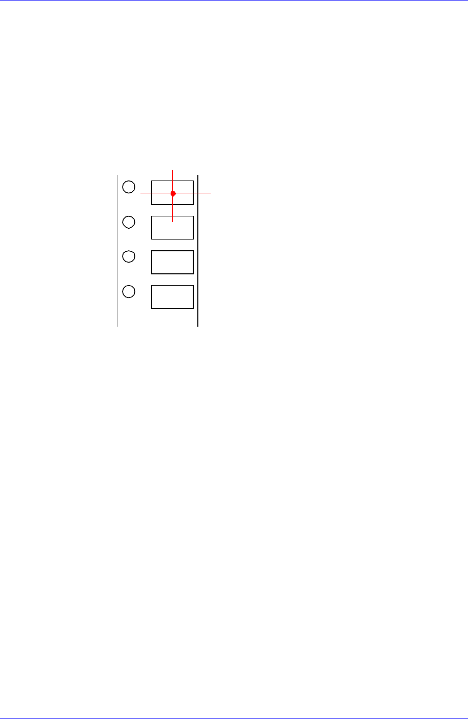
3. Teach the center using the Move Camera (Fiducial Camera) as shown in the
following figure. At this time, teach the pocket center rather than the
component center.
4. Align the cross hair center of the Move Camera (Fiducial Camera) shown on
the vision monitor on the pocket center using the teaching box. Then select
the <21th 8mm Tape Pickup Point> edit box using the mouse and click the
<Get> button to enter the current coordinate in the <21th 8mm Tape Pickup
Point> edit box.
5. Select “Rear” in the <Select> list box and then install the feeder in the 21
st
slot of the feeder base and perform teaching.
<Height Offset> edit box
Set the Z value of the feeder base origin.
<Conveyor Info.> group
Set the data on conveyor.
<Board Flow> combo box
Displays the direction of conveyor movement. To change the direction of
conveyor movement, please contact this machine manufacturer.
<Conveyor Type> combo box
Displays the type of the conveyor. To change the type of the conveyor, please
contact this machine manufacturer.
<AutoMatic Conveyor Width Adjust> group
The method to set up the Conveyor Width Origin is as follows;
1. Perform conveyor homing using the teaching box as shown in the following
figure.
16-10

System Setup
16-11
2. Measure the conveyor width (distance between conveyor frames) accurately
using the measuring device and enter the value in the <Initial Width> edit
box.
3. Click the <Update> button to reflect the changed value.
4. In the Board dialog box, measure the Y value of the PCB to be tested using
the measuring device and enter the value in the <Board Size> group. Then
click the <Conv. Width> button to adjust the conveyor width with the Y
value entered.
Check if there is any foreign matter inside the conveyor, and remove it.
5. Click the <PCB In> and <PCB Out> buttons to check if the test PCB is
conveyed to the placement position and can get out of the conveyor normally.
If there is any problem, perform reset from the start.
6. The default value is used for Width Margin. However, the user may change
the value. In this machine the gap between the conveyor and conveyor belt is
approximately 2mm. Therefore, in case 1mm is entered for the width margin,
the set PCB may stand up.
<Initial Width> Edit box
Sets the initial value of the conveyor width when adjusting the conveyor
width automatically.
<Width Margin> Edit box
Sets the tolerance of the conveyor width.
<Device> combo box
Selects the corresponding device to move the head assembly by rotating the driving
shafts of the X, Y and Z-axes motors, move or rotate the spindle or obtain the current
coordinate of the device to be selected. Available devices are as follows;
Move Cam: Selects Teaching Camera.
Head1: Selects Head1.
Head2: Selects Head2.
Head3: Selects Head3.
Head4: Selects Head4.
Samsung Component Placer CP45FV Administrator’ Guide
Head5: Selects Head5.
Head6: Selects Head6.
Beam: Selects Beam.
<Move> button
Moves the head assembly by rotating the shafts of the X, Y and Z-axes driving
motors using the device selected from the <Device> combo box. At this time, the edit
box corresponding to the position to move to must be clicked on with a mouse.
<Get> button
Reads in the current position of the XY and Z axes of the device selected in <Device>.
At this time, the edit box corresponding to the position to be read must be clicked on
with a mouse.
<Update> button
Transmits the set data to the machine and closes the dialog box.
<Cancel> button
Ignores the set data and closes the dialog box.
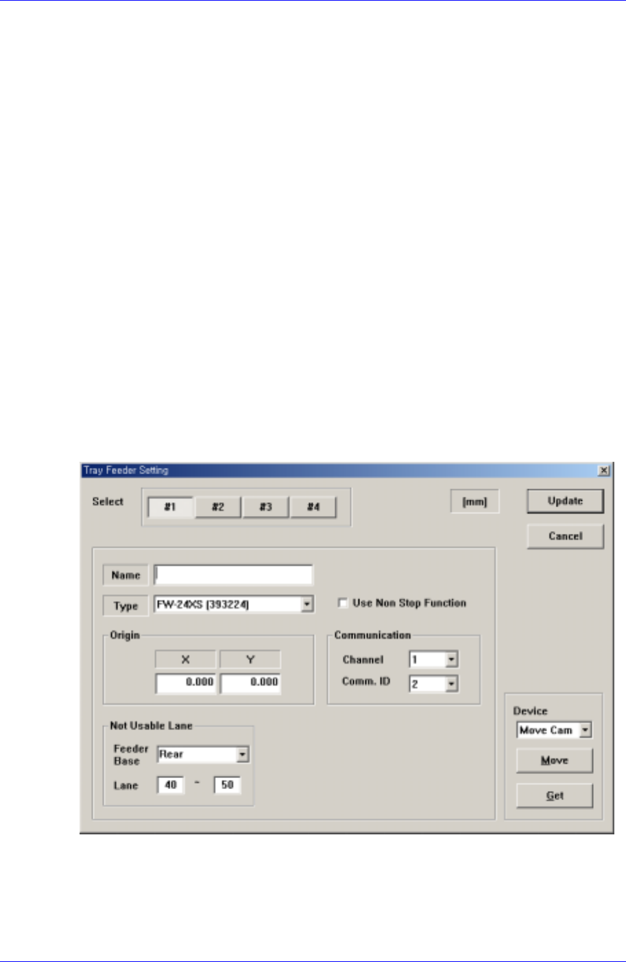
16.5. Tray [F6]
Sets the data on the tray feeder.
When this button is selected, the following dialog box is displayed.
Figure 16-7. “Sys. Setup : Tray Feeder Setting” dialog box
<Select> option button
Select the tray feeder unit. Available tray feeder units are 1 – 4.
That is, a total of four tray feeders can be installed. (For Auto Tray, up to 2 sets of
tray feeders can be installed.)
16-12