Administrator’s Guide(CP45FV) Eng.pdf - 第151页
Feeder Setup 8-19 <Select JEDEC T ray> edit box This brings the information of the tray that will be worked on from the JEDEC tray DB. <Pick> button Executes component pickups from the tray f eeder instal…
Samsung Component Placer CP45FV Series Administrator’s Guide
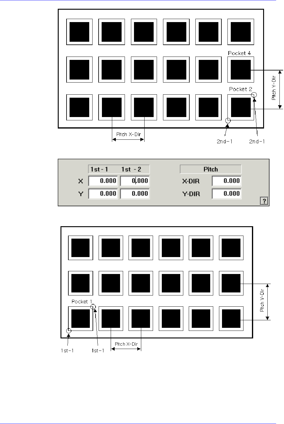
<1Pocket>
As shown in the following figure, input the coordinates of the center point of
pocket No. 1 and the pocket pitch in the X and Y directions.
<JEDEC>
8-18
Feeder Setup
8-19
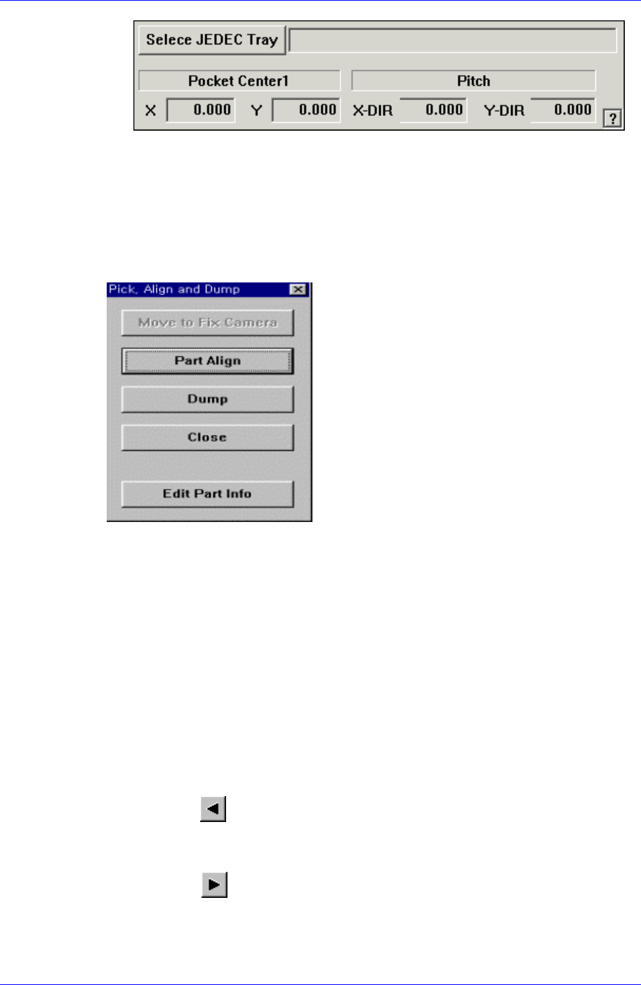
<Select JEDEC Tray> edit box
This brings the information of the tray that will be worked on from the
JEDEC tray DB.
<Pick> button
Executes component pickups from the tray feeder installed on the current line in the
grid. At this time, the device must be selected first. When pickups is successful, the
following dialog box is displayed.
<Move to Fix Camera> button
It is activated only when the corresponding component is aligned by the vision
camera and the alignment camera is the fix camera. When this button is clicked
on, the head block is moved to the fix camera.
<Part Align> button
Executes alignment of the corresponding component.
<Dump> button
Dumps the corresponding component to the specified dump box.
<Close> button
Closes the dialog box.
<Pocket Move> button
Moves the selected device to the pocket number set in <Current Pocket>.
<Move Prev>
button
Moves the selected device to the pocket number previous to the number set in
<Current Pocket>..
<Move Next> button
Moves the selected device to the pocket number next to the number set in <Current
Pocket>.

Samsung Component Placer CP45FV Series Administrator’s Guide
<Current Pocket> group
<X>: Set the pocket number of the tray to move to or pick up from in X direction.
<Y>: Set the pocket number of the tray to move to or pick up from in Y direction.
<Pallet Out> button
Release the pallet to be finished placement from the elevator of the tray feeder.
<Pallet In> button
Loads the pallet to be ready for placement from the elevator of the tray feeder.
<Device> combo box
Selects the corresponding device to move the head assembly by rotating the driving
shafts of the X, Y-axes motors, move or rotate the spindle or obtain the current
coordinate of the device to be selected. Available devices are as follows;
Move Cam: Selects Teaching Camera.
Head1: Selects Head1.
Head2: Selects Head2.
Head3: Selects Head3.
Head4: Selects Head4.
Head5: Selects Head 5.
Head6: Selects Head6.
Beam: Selects Beam.
<Move> button
Moves the head assembly by rotating the shafts of the X, Y-axes driving motors using
the device selected from the <Device> combo box. Before executing “Move”, the cell
in the grid corresponding to the desired position must be clicked on with a mouse.
<Get> button:
Reads in the current position of the XY axis of the device selected in <Device>.
Before executing “Get”, the cell in the grid corresponding to the position to be read
must be clicked on.
<Install to Feeder Base> group
Displays the feeder base unit and slot number when the tray unit is set to the feeder
base.
<Feeder Base>
Displays the feeder base on which the corresponding tray unit is installed
currently. The numbers displayed are as follows.
0: Not installed on any feeder base.
1: Installed on Feeder Base1(Front Feeder Base).
2: Installed on Feeder Base2(Rear Feeder Base).
<Slot No.>
Displays the number of the feeder base slot in which the corresponding tray unit
is installed currently. The numbers displayed are as follows.
0: Not installed in any slot.
1 - 52: Installed in the corresponding number slot.
8-20