Administrator’s Guide(CP45FV) Eng.pdf - 第128页
Samsung Component Placer CP45FV Series Administrator ’ s Guide If there are any missing balls in the ball arrangement, sets the empty balls. It is activated only when the <Grid T y pe> is “ Regular ” . When this bu…

Part Registration
7-43
<Pitch> edit box
Set the distance from the center of a ball to the center of the next ball..
In the case of “Check” or “Rev. Check”, set as if there are balls in the empty area.
<Appear Size> edit box
The ratio between the actual ball size and the size seen in the vision image. For
example, if the value is 1, then the ball is seen in its actual size, and if the value
is 0.9, then the ball is seen at 90% of its actual size.
<Score> edit box
When a ball is searched, the degree of conformity to the specifications is shown
as a score. 1000 means total conformity. But in reality, it is best to use about 600.
If you set a lower value, it can adversely affect recognition. And if you set too
high a score, the rejection rate increases.
<Align Z> edit box
Set the height for recognition. Based on the component surface, if the top is to be
recognizd, set - value and if the bottom is to be recognized, set + value.
<Insp Ball Num> edit box
Select the number of balls to inspect. Available numbers of balls are as follows.
Full: Inspects all balls. It is good for accuracy, but inspection takes long time.
3x3: Inspects 3x3 balls counting from both ends of the corners at opposite angles
of the component.
4x4: Inspects 4x4 balls counting from both ends of the corners at opposite angles
of the component.
5x5: Inspects 5x5 balls counting from both ends of the corners at opposite angles
of the component.
6x6: Inspects 6x6 balls counting from both end of the corners at opposite angles
of the component.
7x7: Inspects 7x7 balls counting from both ends of the corners at opposite angles
of the component.
<Option> group
Set the align option data.
<Area Margin> edit box
Set the limit for the image to be off the center of the screen when the component
is recognized. For example, if this value is 5mm, then the image of the
component should be within 5mm of the center of the screen.
<Tolerance> edit box
Tolerance for the ball. Set it as a percentage of <Ball Pitch>.
<Algorithm> edit box
Select the algorithm for BGA component recognition. Available algorithms are
as follows.
Ball: Recognizes by using the ball only. Used for the BGAs that have distinct
balls as in PBGA.
Ball & Body: Considers both the body and the ball. Used for the BGAs for which
it is difficult to distinguish between the body and the ball as in CBGA.
<Ball Gap…> button
Samsung Component Placer CP45FV Series Administrator’s Guide
If there are any missing balls in the ball arrangement, sets the empty balls. It is
activated only when the <Grid Type> is “Regular”.
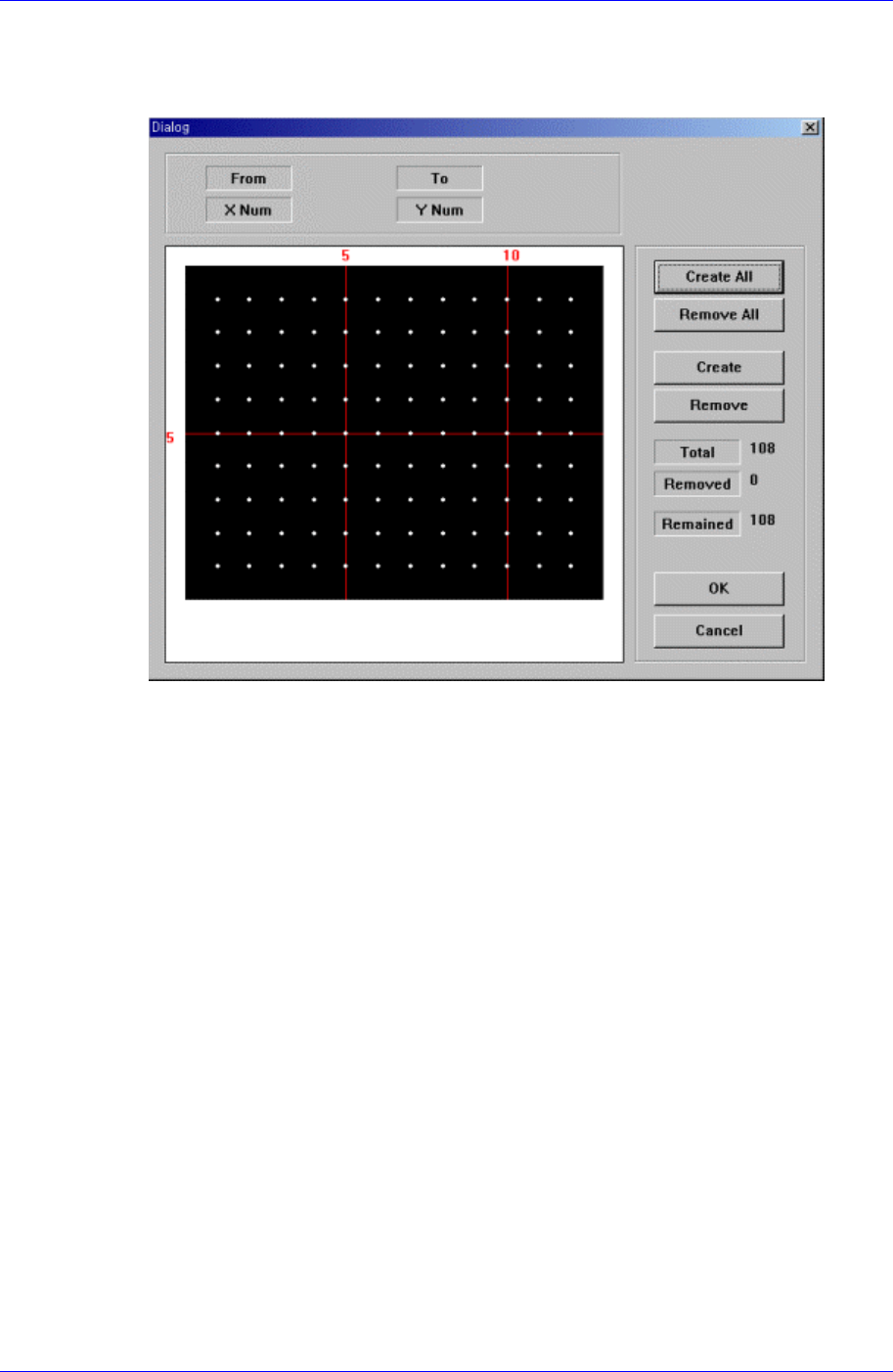
When this button is clicked on, the following dialog box is displayed.
Figure 7-28. “Ball Gap of BGA components-Initial status” dialog box
The grid displays the current ball status. The white dot indicates the ball. To remove
balls in a certain area, the area should be specified first. The area to select can be set
by pressing the left button of the mouse, drag it to the desired area and release it. The
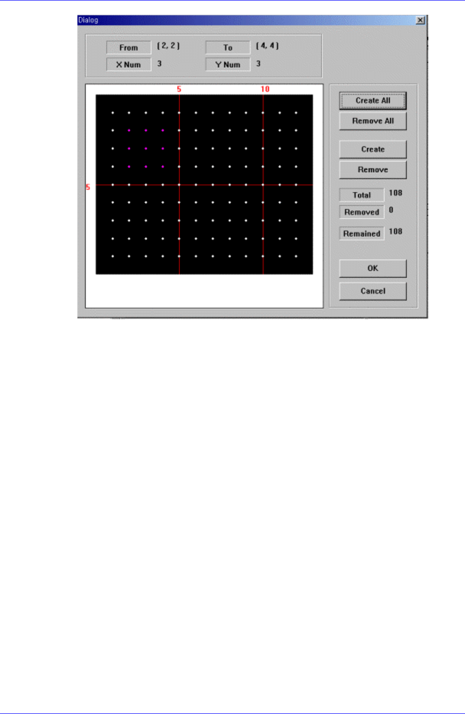
balls in the selected area change color. The following screen shows a case where 25
balls in total, from the ball at (4,4) to the ball at (10,10), 5 balls in X direction and 5
balls in Y direction, are selected.
7-44
Part Registration
7-45
Figure 7-29. “Ball Gap of BGA component-when there is a selected area” dialog box
<Create All> button
Creates all balls.
<Remove All> button
Removes all balls.
<Create> button
Creates balls in the selected area.
<Remove> button
Removes the balls in the selected area.
When the balls in the selected area are removed, the screen looks as follows.