Administrator’s Guide(CP45FV) Eng.pdf - 第261页
Machine Calibration 15-23 5. If the message, “Get tool from ANC to Head1. T o Get it, Click [Next]” is displayed, click the <Next> bu tton. Then the calibration nozzle is mounted on the head while the Z-axis is mov…
Samsung Component Placer CP45FV Administrator’s Guide
<Head - Fly Offset> button
Calibrates the offset of the fly camera. To perform this procedure, arrange the
calibration nozzle on the ANC1 pocket.
Here, measure the offset from the nozzle center to the center of the
component to be recognized.
The Fly Camera offset calibration procedure is as follows;
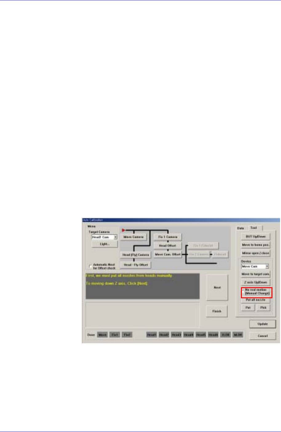
1. Do not select the <No Real Motion [Manual]> check box as shown in
the following figure, or the nozzle will have to be mounted on or
removed from the head manually.
2. If there is a nozzle on the head, click the <Put> button in the ANC dialog
box and place the nozzle on the pocket.
3. Click the <Head-Fly Offset> button in the menu group of the Auto
Calibration dialog box.
4. If the message, “First, we must put all nozzles from heads manually. To
moving down Z axis, Click [Next].” is displayed, click the <Next>
button.
15-22
Machine Calibration
15-23
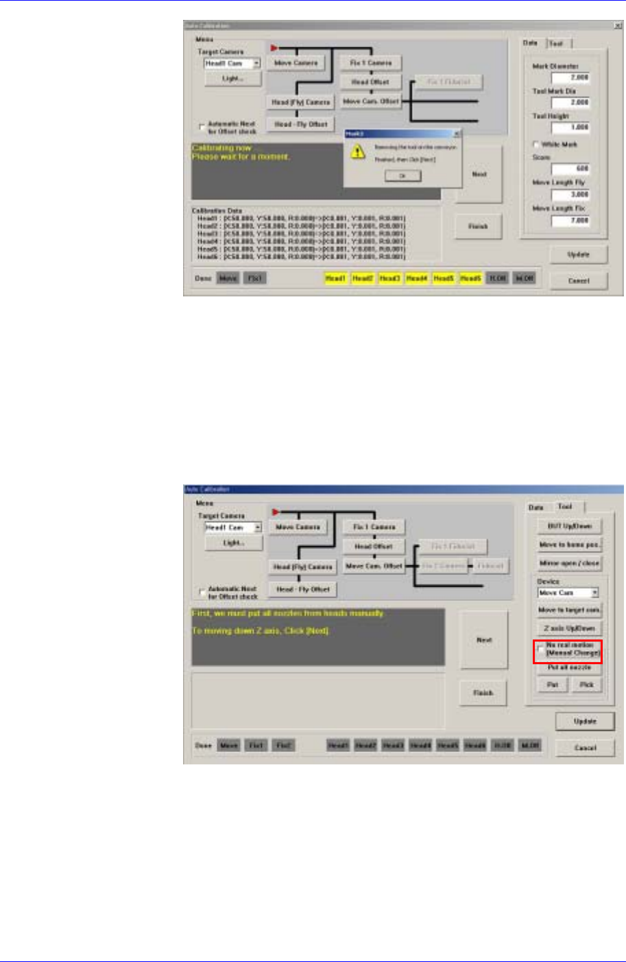
5. If the message, “Get tool from ANC to Head1. To Get it, Click [Next]”
is displayed, click the <Next> button. Then the calibration nozzle is
mounted on the head while the Z-axis is moving down.
6. If the message, “Up to align height and mirror close. To move, click
[Next]” is displayed, click the <Next> button. Then the Z-axis of the
head is moved to the calibration position, closing the mirror.
7. If the message, “Calibration is prepared. To Calibrate, Click [Next].” is
displayed, click the <Next> button. Then the calibration is performed.
8. When the calibration is completed, the calibration value is displayed.
9. Perform the calibration for the other heads from Head2 to Head6 in the
same manner.
10. When the above procedure is completed, click the <Update> button to
apply the changed value.
<Fix 1 Camera> button
Calibrates the fix camera. To perform this procedure, arrange the calibration
nozzle on the ANC 1 pocket.
The fix camera calibration procedure is as follows;
1. Click the <Calibration> button in the Camera Setting dialog box.
2. Display the Auto Calibration dialog box and click the <Fix Camera>
button in the <Menu> group.
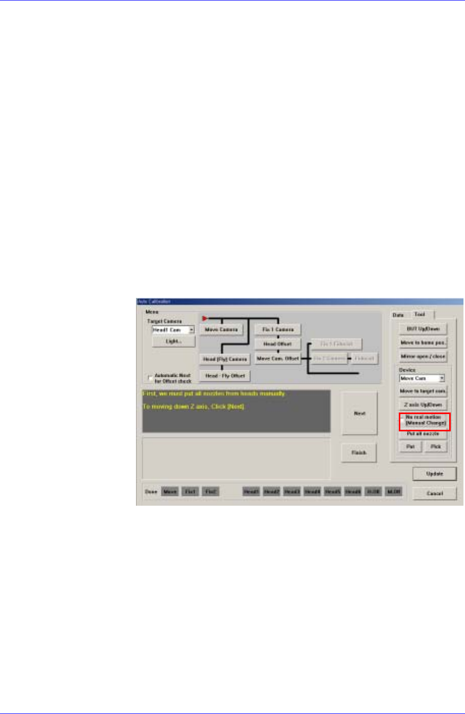
3. Do not select the <No Real Motion [Manual]> check box as shown in
the following figure, or the nozzle will have to be mounted on or
removed from the head manually.
4. If there is a nozzle on the head, click the <Put> button in the ANC dialog
box and place the nozzle on the pocket.
5. If the message, “First, we must put all nozzles from heads manually. To
moving down Z axis, Click [Next].” is displayed, click the <Next>
button.
6. If the message, “Get tool from ANC to Head1. To get it Click [Next]” is
displayed, click the <Next> button. Then the calibration nozzle is
mounted on the head while the Z-axis is moving down.
Samsung Component Placer CP45FV Administrator’s Guide
7. If the message, “Move to center position of [Fix 1] camera. To move,
Click [Next].” is displayed, click the <Next> button. Then the Head 1
moves to the center of the fixed camera.
8. Adjust the lighting value of the <Default Light> group so that the
fiducial mark of the calibration nozzle is mounted on the head 시오.
9. If the message, “Calibration is prepared. To Calibrate, Click [Next].” is
displayed, click the <Next> button. Then the calibration begins.
10. Once the calibration is completed, the Camera Calibration Date dialog
box is displayed and the calibration data are shown. At this time, it will
ask whether to perform update. Click the <OK> button when updating
the calibration information.
<Head Offset> button
Calibrates the offset of the head. To perform this procedure, arrange the
calibration nozzle on the ANC 1 pocket.
The head offset calibration procedure is as follows;
1. Click the <Calibration> button in the Camera Setting dialog box.
2. Do not select the <No Real Motion [Manual]> check box as shown in
the following figure, or the nozzle will have to be mounted on or
removed from the head manually.
3. If there is a nozzle on the head, click the <Put> button in the ANC dialog
box and place the nozzle on the pocket.
4. Click the <Head Offset> button in the menu group of the Auto
Calibration dialog box.
5. If the message, “First, we must put all nozzles from heads to ANC. To
put, Click [Next]” is displayed, click the <Next> button.
6. If the message, “Get tool from ANC to Head1. To get it, Click [Next]” is
displayed, click the <Next> button. Then the calibration nozzle is
mounted on the head while the Z-axis is moving down.
7. If the message, “Move to center position of [Fix 1] camera. To move,
Click [Next].” is displayed, click the <Next> button. Then the Head 1
moves to the center of the fixed camera. At this time the machine is
already recognizing the fixed camera position through the previous fixed
15-24