N7201A618E00_0309.pdf - 第16页
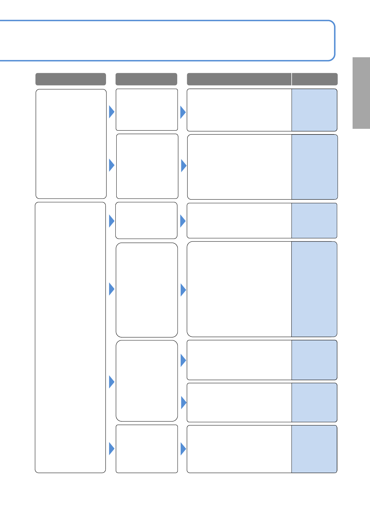
NPM-W 2 EJM7DE-MB-01T-00 Misaligned placement Nozzle error See 1-1-1-2 [Pickup error , Stand pickup] Component data error What if Troubleshoo ting 1-1-2 Placement er r or 1 1-1-2 -1 Pickup c ondition error 1-1-1-1 to 1-1…
NPM-W2 EJM7DE-MB-01T-00
Pickup error,
Stand pickup
(confirmation
items when the
pickup rate
decreases)
Feeder error
1-1-1-1 to1-1-1-2
See [Cannot pickup]
Nozzle selection
error
1-1-1-2
Nozzle error
Pickup condition
error
Check the vacuum pressure
(appropriate pressure:-100 to
-87kPa). If it is not within the
Value, adjust the pressure.
Check the pickup position setting.
Adjust if incorrect.
1-1-1-1 to 1-1-1-2
See [Cannot pickup]
Nozzle selection
error
Check whether the appropriate
nozzle has been selected
(component type and size).
If not, replace nozzle.
Tape splicing error
Cannot pickup
Problem Cause
Check/Solution Reference
Operating
procedure
3-2-6
6-1-13
9-1-6
Maintenance
6-5
1.Check whether proper splicing
has been done. Adjust if
necessary.
2.Check whether the same
components are properly joined.
Adjust if necessary.
Tape Splicing
Operating
Instructions
2
1.Make sure that there is no
clogging, wearing down, or
chipping of the nozzle tip.
Replace the nozzle if you find
anything wrong with it.
2.Check for a sliding error of the
nozzle holder. Modify if
necessary.
3.Check whether the nozzle is
magnetized or not .
Demagnetize it if magnetized.
Maintenance
4-1-1
Operating
procedure
6-2-4, 6-2-6,
6-2-8
What if
‐
‐
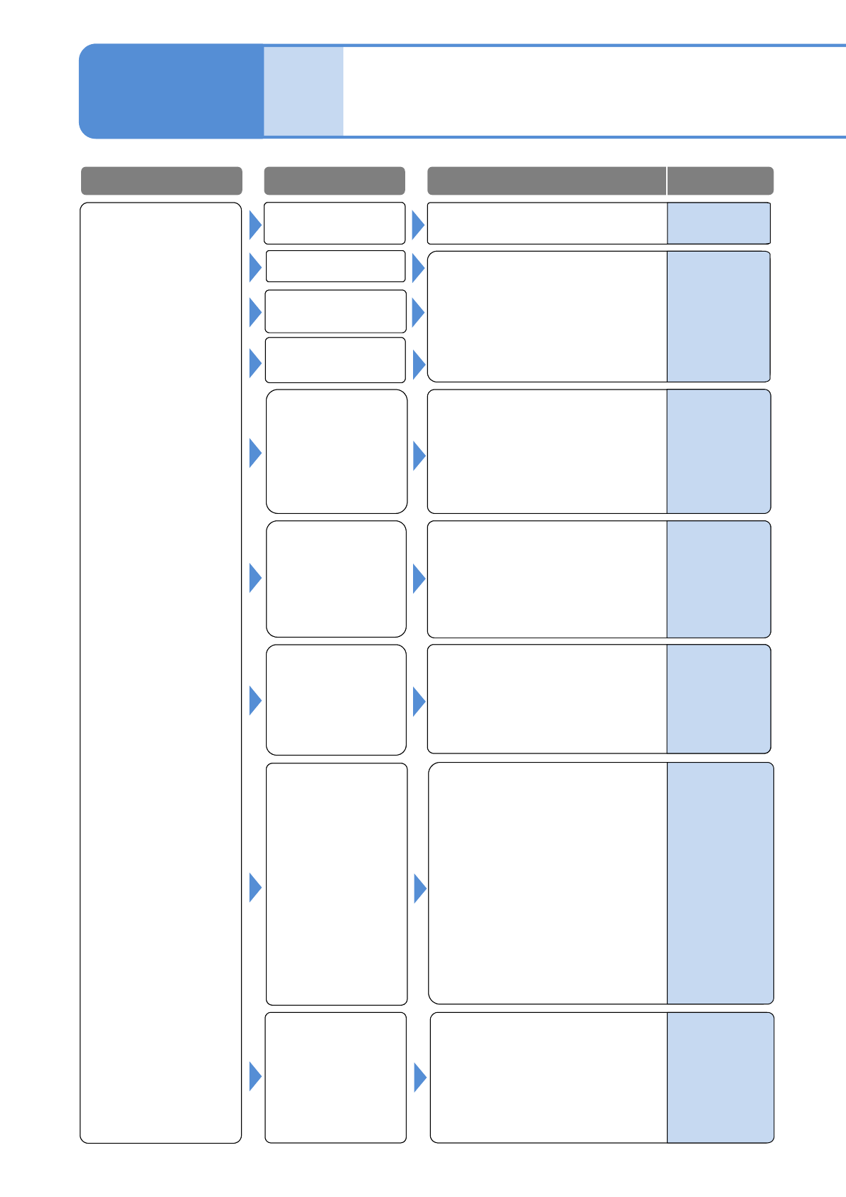
NPM-W2 EJM7DE-MB-01T-00
Misaligned
placement
Nozzle error
See 1-1-1-2
[Pickup error, Stand pickup]
Component data
error
What if
Troubleshooting
1-1-2
Placement error 1
1-1-2-1
Pickup condition
error
1-1-1-1 to 1-1-1-2
See [Cannot pickup]
Check whether the PCB support
pins are properly positioned.
Adjust if necessary.
(Check that the PCB support pin
does not interfere with the
component)
Check the PCB upper surface
warpage.
If it warps too much, do not use it.
Placement
condition error
Nozzle selection
error
Feeder error
PCB support
setting error
Poor PCB
Error in setting the
height of the placed
component
(interference with the
placed component)
Check whether the placed
component height is set up
properly.
Fix it if necessary.
Problem Cause
Check/Solution Reference
Operating
procedure
2-5-3
Operating
procedure
9-1-4
DGS
Programming
Manual
4
DGS
Programming
Manual
6
1.Check whether the placement
retainer is set up properly. Fix it
if necessary.
2.Check whether the vacuum
breaking pressure is set properly.
Adjust it as needed.
3.Check whether XY coordinates
of the production data is set up
properly. Adjust it if not correct.
4.Check for the placement timer
value.
Check whether component outline
and thickness, and dimensions of
each electrode are input correctly.
Adjust them if incorrect.
-
-
-
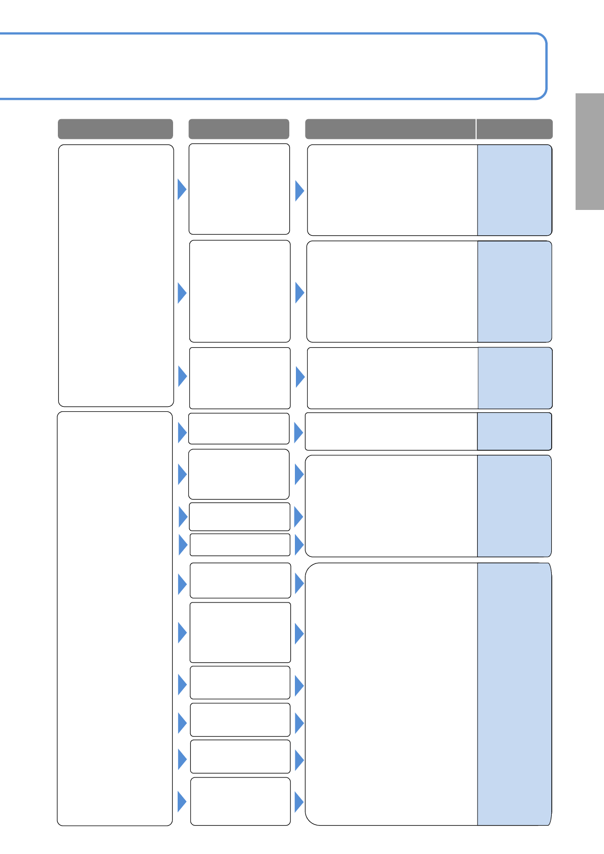
NPM-W2 EJM7DE-MB-01T-00
Component
missing
Nozzle error
See 1-1-1-2
[Pickup error, Stand pickup]
Error in setting the
height of the placed
component
(interference with the
placed component)
1-1-2-2
Pickup condition
error
1-1-1-1 to 1-1-1-2
See [Cannot pickup]
See 1-1-2-1 to 1-1-2-2
[Misaligned placement]
Tape splicing error
PCB support setting
error
PCB mark
recognition error
Component data
error
Placement
condition error
Solder printing
condition error
(printer)
Recognition error
(misalignment, tilt)
PCB mark
recognition error
Solder printing
condition error
(printer)
Check the printing condition and
adjust the printer.
Misaligned
placement
Problem Cause
Check/Solution Reference
DGS
Programming
Manual
5
-
1.Adjust if the PCB mark setting
(coordinate, shape and
dimensions) are incorrect.
2.Correct the PCB stop position if
is aligned.
(e.g., check the length f the
placed component extending ff
the board)
-
What if
1.Check the recognition image
(center and tilt) and an image of
an electrode. Adjust if necessary.
2.If the cover glass of the multi-
recognition camera is
contaminated, wipe it off.
-
-
-
Supply unit (feeder
or tray) setting error
or defect