N7201A618E00_0309.pdf - 第292页
NPM-W 2 EJM7DE-MB-03T-00 Recog- nition error message Troubleshooting 3-2-1 Recognition er ror c ode (num ber) ca n be use d for ch ecking of recognition er ror in formation. The table belo w is the list o f the rec ognit…
NPM-W2 EJM7DE-MB-03T-00
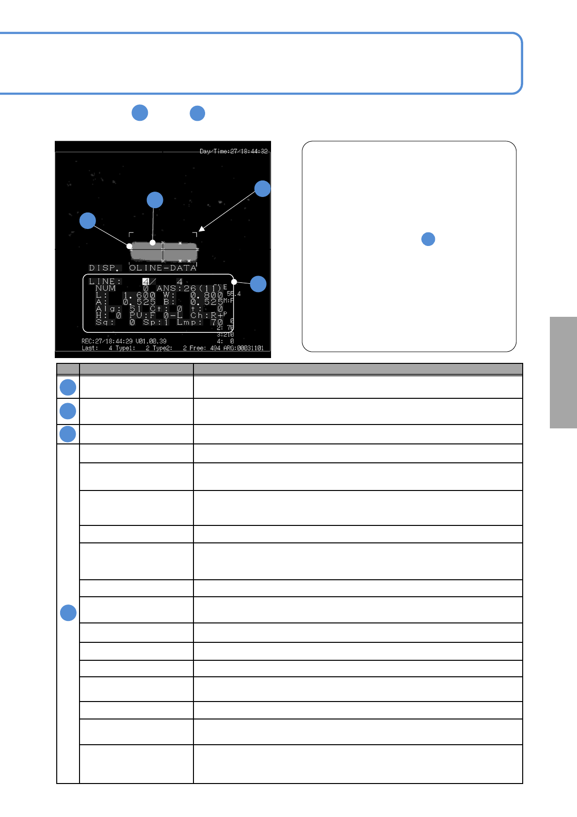
The meanings of through on the following recognition error screen are shown in the table below.
This allows you to identify the cause of a recognition error as stated in “ Example of recognition error.”
3-1-1-2
No. Name Description
Chip data dimensions
Displays the component outline size that is determined according to the preset
component shape data.
Outline
Shows the outline or image condition of a recognition target
(The image is displayed, with information thinned out for records)
Feature Displays the features extracted (Up to 20)
LINE (Current error screen number) / (The number of recording error screens)
NUM
Number of outlines
Indicates the number of outline pixels of the target part.
ANS
Recognition result status
In case of a recognition error, the error information can be identified by the code
L, W Chip size data (X direction in length), W(Y direction in width)
A, B
Reference information
Reference value of recognition error information is stored.
Information varies depending on the recognition result code.
Alg Internal algorithm identification number
Ct
Feature points
Displays the feature points extracted.
t Image threshold information
H Nozzle number or head number
PU Unit number
Ch
Stage of use, scan direction
F: forward, R: retreat +: forward direction scan , -: backward direction scan
Sq Placement sequence
Sp
Multi-recognition camera scan speed
1: Low, 2: Middle, 3:High
Lmp
Lamp value that is mainly used.
Transmitted lighting lamp value is used for transparency recognition and reflective
lighting lamp value for reflection recognition.
A
A
B
B
C
C
D
D
Example of recognition error
In the example left, [ANS (recognition result status)
26] is displayed. If you see the code 26 in the page 3-
2-1-4, you can find that W (Y direction in width) is
wrong.
In addition, the width of the component image is
smaller than the frame (L (X direction in length), W) of
the specified shape data size
Therefore, it is considered that the recognition error
was caused by the following:
1)Incorrect setting of component
(component setting error)
2) Size error of the component electrode data
3) Component pickup condition error
This enables you to find the cause of errors easily.
A
D
A
■
■
Solutions to
recognition
NPM-W2 EJM7DE-MB-03T-00
Recog-
nition
error
message
Troubleshooting
3-2-1
Recognition error code (number) can be used for checking of recognition error information.
The table below is the list of the recognition error information. For details, see the ‘Individual item’.
3-2-1-1
Recognition error number category
Errors are categorized as the recognition error code (number) below.
For individual items, the rated values vary depending on the reference. See the corresponding ‘Individual
item’.
1 to 49 :
Indicates recognition error
50 :
Indicates that teach recognition is properly ended by teach.
51 to 100 : Indicates that recognition is properly ended. (Normally 100)
The number indicates the matching rate recognized with the template. The higher
value shows the higher template match rate.
How to use recognition error information
The error code (number) of the recognition result is classified as the following categories.
Category Description
Error code
(number)
1)Parameter/
recognition coarse
detection processing
errors
Errors that arise due to matters associated with the
setting parameters or the pickup state. Check for the
created data, the pickup state, and the image conditions.
11,12,13,14,15,16,17,
18,19,20
2)Recognition target
detection result
errors
Indicates error evaluation on component detection
results. Check the state of components.
21,22,25,26,27,28,29,
30
3)Individual
electrode shape/
electrode state
errors
Errors that arise due to abnormal electrode state or
positional relation between the electrodes. Check for the
state of components and the setting conditions for the
lamp.
31,32,33,34,35,36,37,
38,39,40
4)Other/Individual
evaluation/
designated item
errors
Errors that arise due to check items individually
designated and the outline state of components. Check
for the state of components and the designated check
data.
41,42,43,45,46,47,49
Recognition error
message lists 1
NPM-W2 EJM7DE-MB-03T-00
3-2-1-2
Explaining the details of recognition error
The details of recognition error are composed of “Code,” “Description,” “Cause,” and “Solution.”
Because there are thought to be several “Causes,” select an appropriate cause and take the corresponding
solution.
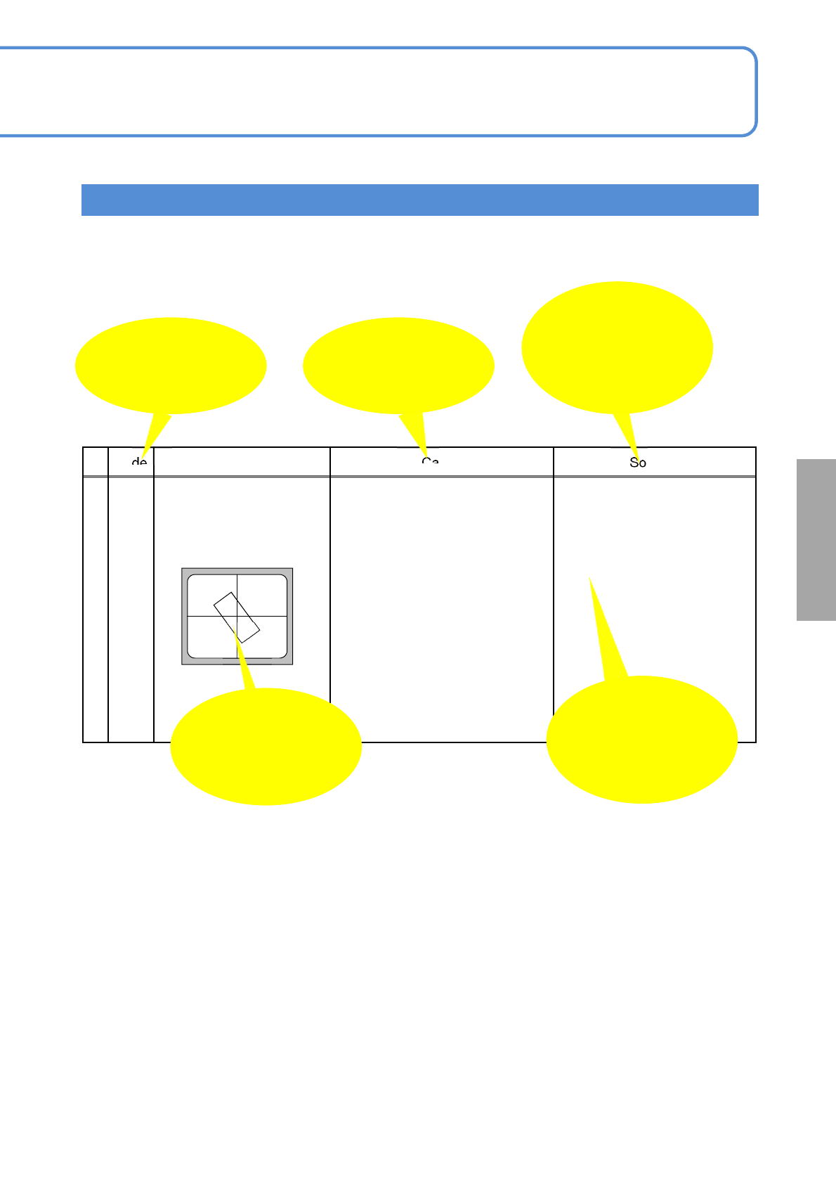
Code Description Cause Solution
21
Component recognition
angle error
<Example of an image>
1) Unacceptable recognition angle Check on the component
height, pickup position, pickup
offset and nozzle of use to
stabilize the pickup condition.
Check the supply angle.
Items are displayed
as changes in data
are required.
An estimated
image on the
recognition error
screen
Recognition error
code
(ANS: or A:)
Probable causes of
the error
Confirmation and
solution items for
causes stated on
the left
Recognition target detection result errors
Solutions to
recognition