N7201A618E00_0309.pdf - 第290页
NPM-W 2 EJM7DE-MB-03T-00 Recog- nition informat -ion Troubleshooting 3-1-1 Because the mac hine stores past recognition e rrors , you can c onfirm e rror information after production has finished. Please use stored infor…

3 Solution to recognition
NPM-W2 EJM7DE-MB-03T-00
Recog-
nition
informat
-ion
Troubleshooting
3-1-1
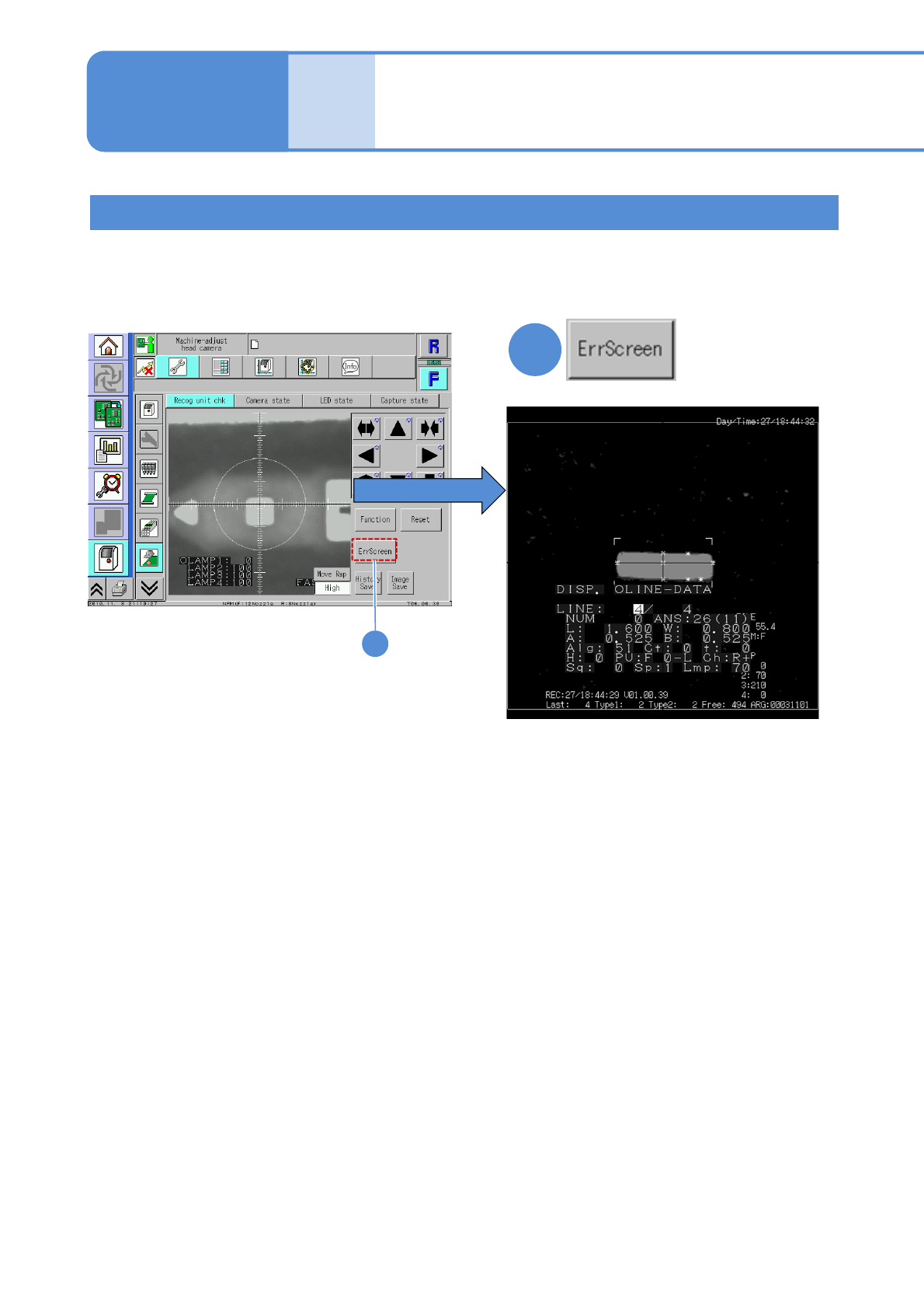
Because the machine stores past recognition errors, you can confirm error information after production has
finished. Please use stored information for your error solutions. (Up to 500 error images can be stored for a
stage.) For how to get and operate this screen, see P. 7-2-11 in the Operating procedure.
1
3-1-1-1
Pressing the [ErrScreen] causes the error
information to appear on the screen.
(To the next page)
Recognition error screen
1
Recognition information
after production
(memory function)
NPM-W2 EJM7DE-MB-03T-00
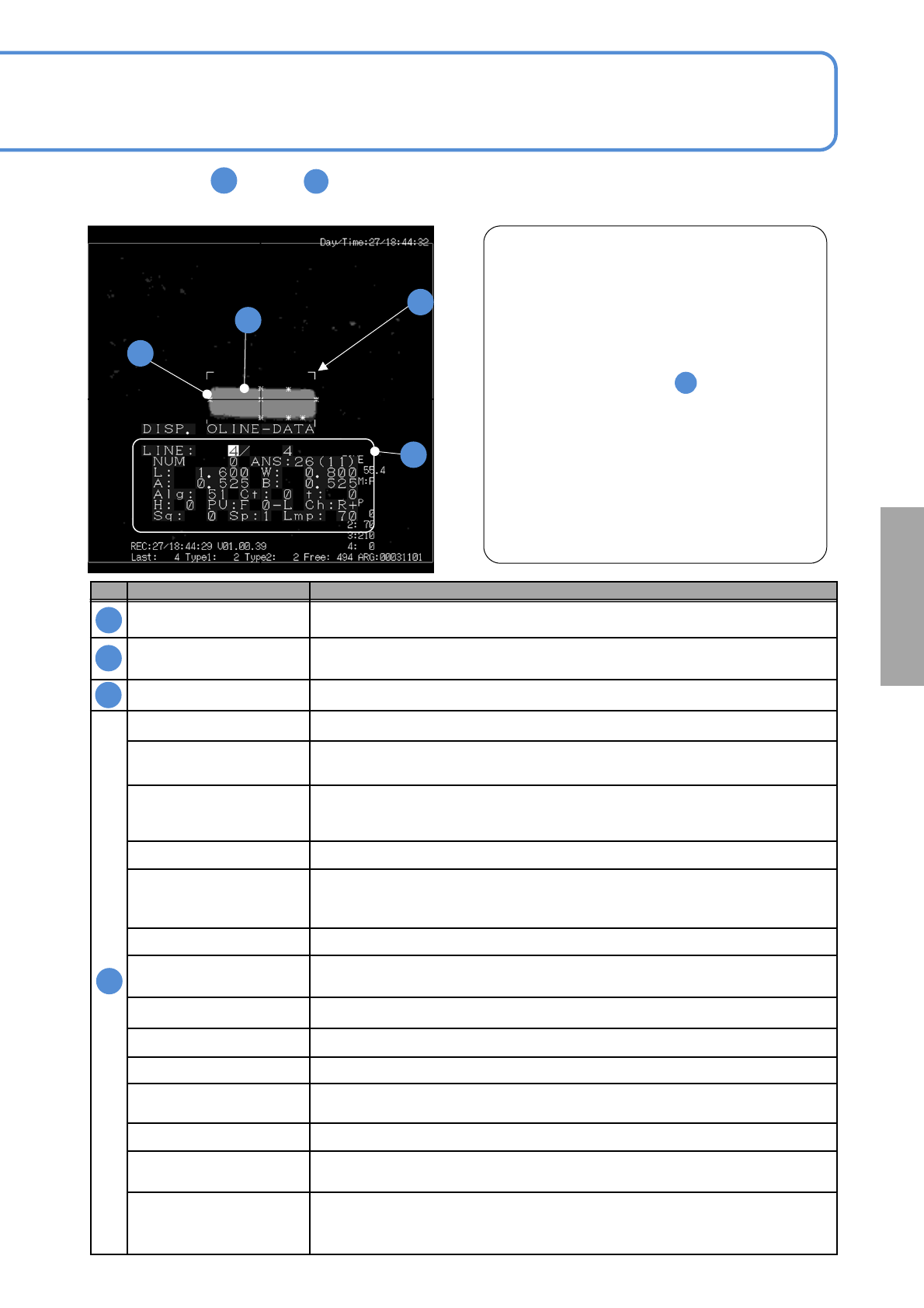
The meanings of through on the following recognition error screen are shown in the table below.
This allows you to identify the cause of a recognition error as stated in “ Example of recognition error.”
3-1-1-2
No. Name Description
Chip data dimensions
Displays the component outline size that is determined according to the preset
component shape data.
Outline
Shows the outline or image condition of a recognition target
(The image is displayed, with information thinned out for records)
Feature Displays the features extracted (Up to 20)
LINE (Current error screen number) / (The number of recording error screens)
NUM
Number of outlines
Indicates the number of outline pixels of the target part.
ANS
Recognition result status
In case of a recognition error, the error information can be identified by the code
L, W Chip size data (X direction in length), W(Y direction in width)
A, B
Reference information
Reference value of recognition error information is stored.
Information varies depending on the recognition result code.
Alg Internal algorithm identification number
Ct
Feature points
Displays the feature points extracted.
t Image threshold information
H Nozzle number or head number
PU Unit number
Ch
Stage of use, scan direction
F: forward, R: retreat +: forward direction scan , -: backward direction scan
Sq Placement sequence
Sp
Multi-recognition camera scan speed
1: Low, 2: Middle, 3:High
Lmp
Lamp value that is mainly used.
Transmitted lighting lamp value is used for transparency recognition and reflective
lighting lamp value for reflection recognition.
A
A
B
B
C
C
D
D
Example of recognition error
In the example left, [ANS (recognition result status)
26] is displayed. If you see the code 26 in the page 3-
2-1-4, you can find that W (Y direction in width) is
wrong.
In addition, the width of the component image is
smaller than the frame (L (X direction in length), W) of
the specified shape data size
Therefore, it is considered that the recognition error
was caused by the following:
1)Incorrect setting of component
(component setting error)
2) Size error of the component electrode data
3) Component pickup condition error
This enables you to find the cause of errors easily.
A
D
A
■
■
Solutions to
recognition