N7201A618E00_0309.pdf - 第18页
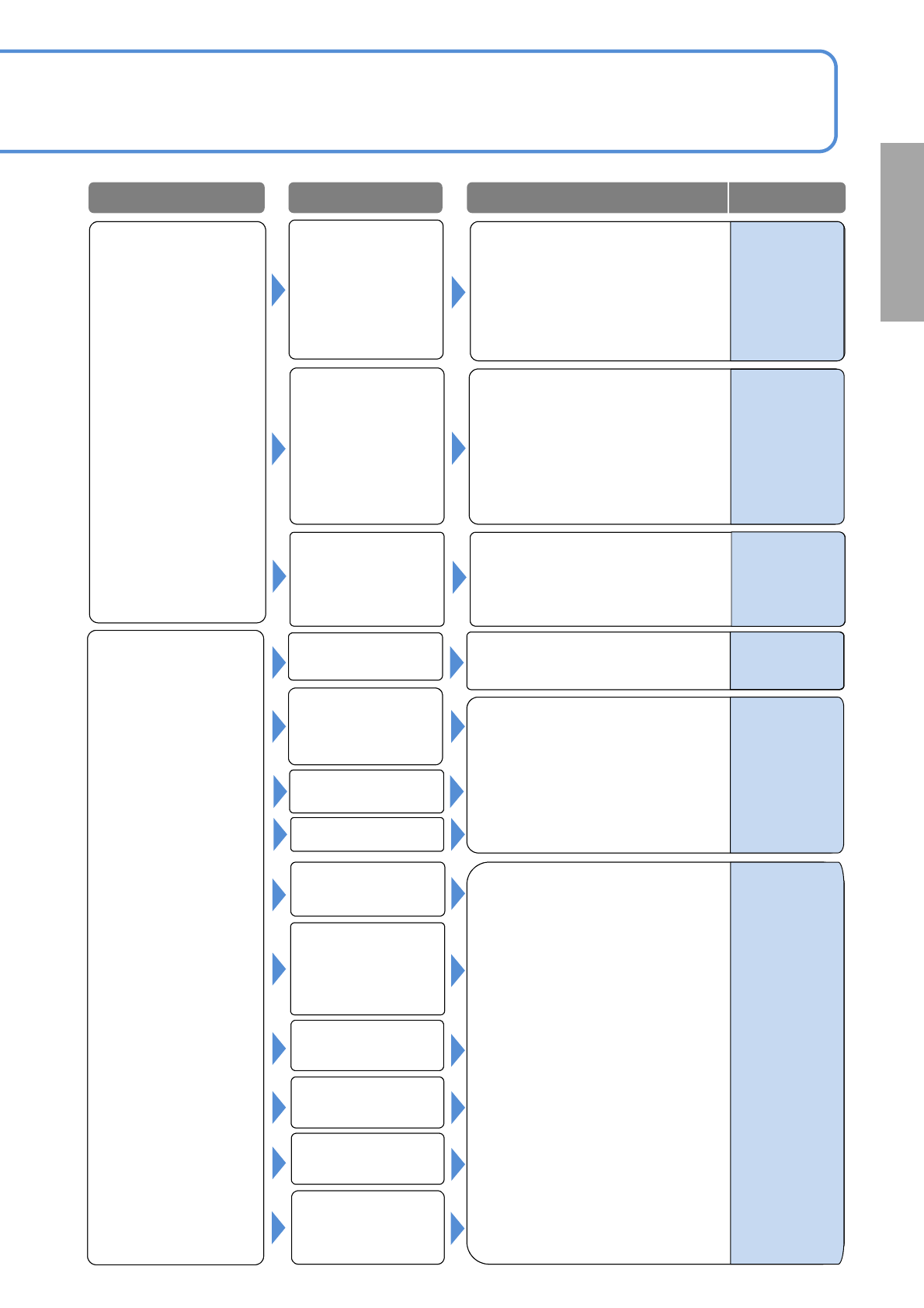
NPM-W 2 EJM7DE-MB-01T-00 Wrong placement Nozzle error See 1-1-1-2 [Pickup er ror , Stand p ickup] What if Troubleshoo ting 1-1-2 Placement er r or 2 1-1-2 -3 1-1-1-1 to 1-1-1-2 See [Cannot p ickup] See 1-1-2-1 to 1-1-2-2…
NPM-W2 EJM7DE-MB-01T-00
Component
missing
Nozzle error
See 1-1-1-2
[Pickup error, Stand pickup]
Error in setting the
height of the placed
component
(interference with the
placed component)
1-1-2-2
Pickup condition
error
1-1-1-1 to 1-1-1-2
See [Cannot pickup]
See 1-1-2-1 to 1-1-2-2
[Misaligned placement]
Tape splicing error
PCB support setting
error
PCB mark
recognition error
Component data
error
Placement
condition error
Solder printing
condition error
(printer)
Recognition error
(misalignment, tilt)
PCB mark
recognition error
Solder printing
condition error
(printer)
Check the printing condition and
adjust the printer.
Misaligned
placement
Problem Cause
Check/Solution Reference
DGS
Programming
Manual
5
-
1.Adjust if the PCB mark setting
(coordinate, shape and
dimensions) are incorrect.
2.Correct the PCB stop position if
is aligned.
(e.g., check the length f the
placed component extending ff
the board)
-
What if
1.Check the recognition image
(center and tilt) and an image of
an electrode. Adjust if necessary.
2.If the cover glass of the multi-
recognition camera is
contaminated, wipe it off.
-
-
-
Supply unit (feeder
or tray) setting error
or defect
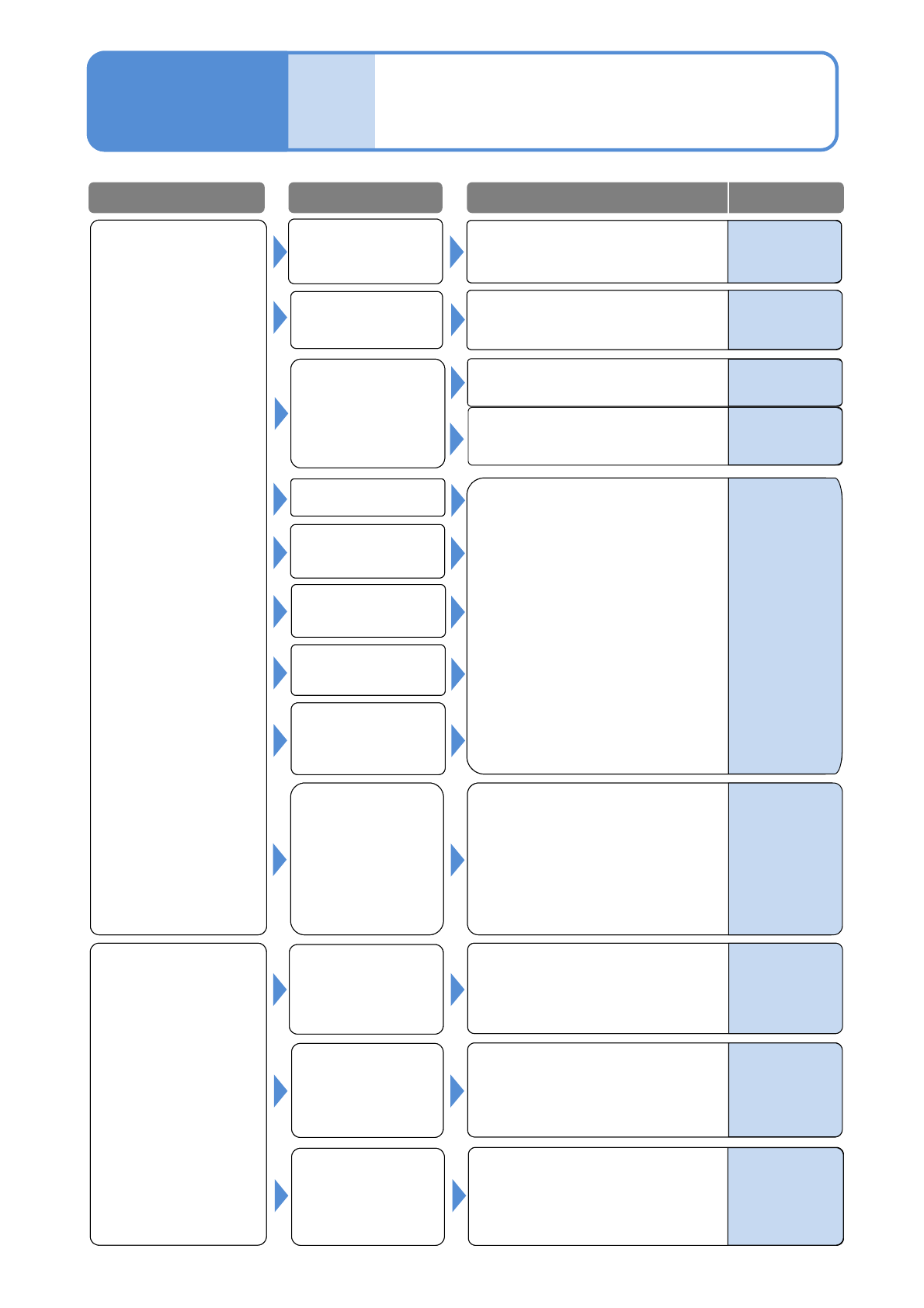
NPM-W2 EJM7DE-MB-01T-00
Wrong placement
Nozzle error
See 1-1-1-2
[Pickup error, Stand pickup]
What if
Troubleshooting
1-1-2
Placement error 2
1-1-2-3
1-1-1-1 to 1-1-1-2
See [Cannot pickup]
See 1-1-2-1 to 1-1-2-2
[Misaligned placement]
Pickup condition
error
PCB support
PCB mark
recognition error
Component data
error
Placement
condition error
Solder printing
condition error
(printer)
Component
ejection error
PCB recognition
mark data error
Check and adjust the PCB
recognition data (shape set) as
necessary.
Turn OFF the servo switch, remove
the PCB, and clean the recognition
mark.
Error in setting the
length of the placed
component extending
off the board
The PCB
recognition mark is
contaminated
PCB recognition
error
Problem Cause
Check/Solution Reference
DGS
Programming
Manual
5
-
1.Check the setting value
(applicable value: 0.13 to
0.14MPa) of the cleaning blow
pressure. If it is not within the
value, modify the pressure.
2.Check the nozzle contamination.
If contaminated, clean the nozzle.
Check the length of the placed
component extending off the
board.
Maintenance
4-1-1,6-5
-
-
-
Supply unit (feeder
or tray) setting
error or defect
-
Operating
procedure
6-1-2
Operating
procedure
2-4-1
Check for misfeeding of
components, and be sure to mount
correct components.
1-1-1-1 to 1-1-1-2
See [Cannot pickup]
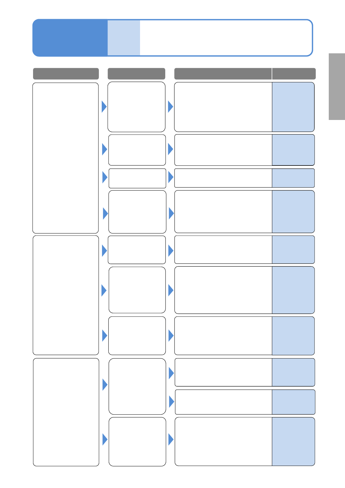
NPM-W2 EJM7DE-MB-01T-00
The PCB detection
sensor on the
conveyor does not
detect the PCB.
(There is a cutout or
a slit at a detection
point.)
What if
Troubleshooting
1-1-3
Transfer error
1-1-3-1
Error in setting the
length of the placed
component extending
off the board
The PCB detection
sensor on the
upstream process
conveyor does not
detect the PCB.
Check the sensor for contamination.
If contaminated wipe it off.
Two PCBs are
loaded.
Check the PCB unloading signal
(BA signal) of the upstream
process. Adjust as necessary.
1.Check the alignment of the
conveyor coupling to the
upstream process. If necessary,
adjust the alignment.
2.Check the belt or the guide.
If it is contaminated, wipe it off.
The PCB stays on
the conveyor.
The PCB stays on
the entrance of the
upstream process.
PCB transfer error
A belt or a guide is
contaminated.
Clean the belt or the guide.
The PCB detection
sensor on the
conveyor detects
the PCB although it
does not exist.
Check the sensor for
contamination. If contaminated
wipe it off.
PCB loading error
The PCB request
signal of the
downstream
process does not
turn OFF within
the PCB unloading
waiting time
Check the PCB request signal
(READY signal) of the downstream
Process output.
Check the PCB unloading waiting
time. Adjust if necessary.
PCB unloading
error
Problem Cause
Check/Solution Reference
Operating
procedure
6-1-2
Maintenance
6-6
Maintenance
6-10
Maintenance
6-10
–
–
–
–
–
Check the slit size of the PCB.
(Use within the limit of the notch
allowable dimension.)
1.Check the alignment of the
conveyor coupling to the
downstream process. If
necessary, adjust it.
2.Check the belt or the guide. If it is
contaminated, wipe it off.
Check the length of the placed
component extending off the
board.
–
What if