sh030106u.pdf - 第10页
1 CONTENTS 1. FUNCTIONS AND CONF IG URATION 1- 1 to 1-52 1.1 Summary ........................................................................................................................................... 1- 1 1.2 Fu…
A - 8
«Wiring»
Wires mentioned in this Instruction Manual are selected based on the ambient temperature of 40 °C.
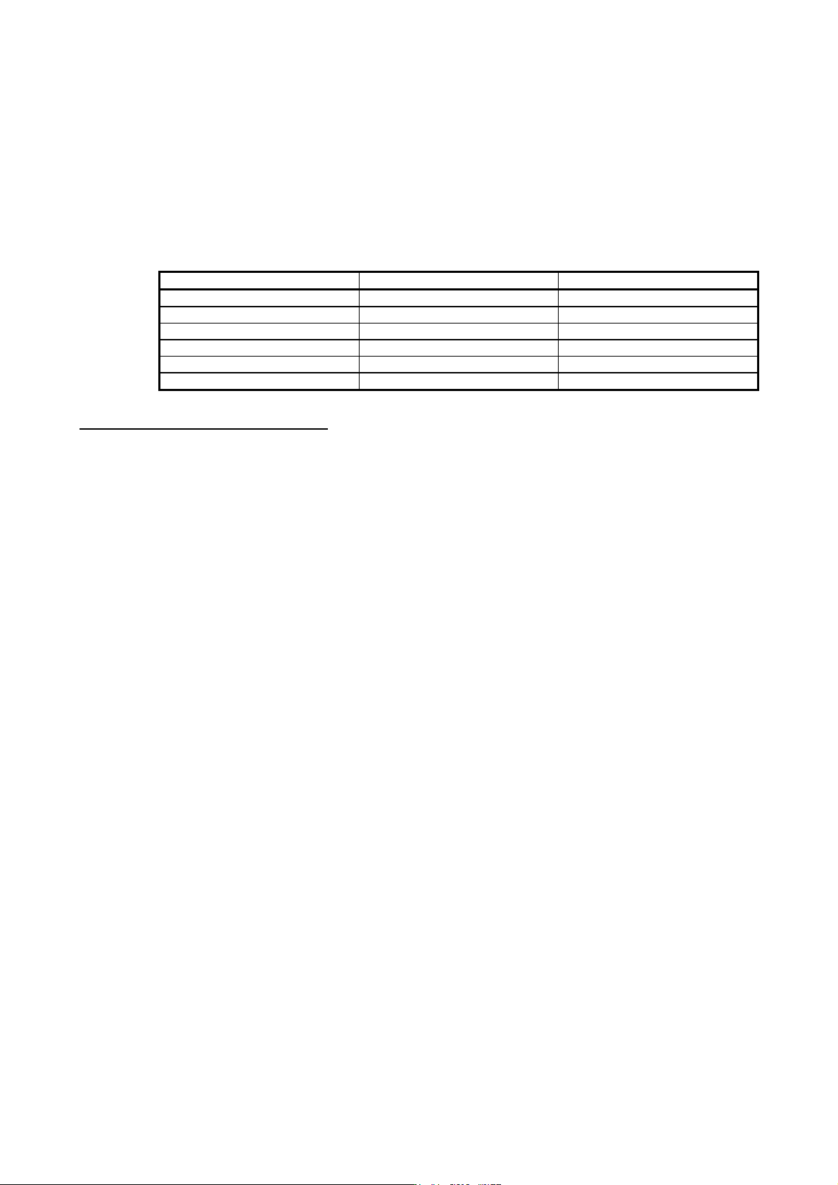
«U.S. customary units»
U.S. customary units are not shown in this manual. Convert the values if necessary according to the
following table.
Quantity SI (metric) unit U.S. customary unit
Mass 1 [kg] 2.2046 [lb]
Length 1 [mm] 0.03937 [inch]
Torque 1 [N•m] 141.6 [oz•inch]
Moment of inertia 1 [(× 10
-4
kg•m
2
)] 5.4675 [oz•inch
2
]
Load (thrust load/axial load) 1 [N] 0.2248 [lbf]
Temperature N [°C] × 9/5 + 32 N [°F]
Global standards and regulations
Compliance with the indicated global standards and regulations is current as of the release date of this
manual. Some standards and regulations may have been modified or withdrawn.

1
CONTENTS
1. FUNCTIONS AND CONFIGURATION 1- 1 to 1-52
1.1 Summary ........................................................................................................................................... 1- 1
1.2 Function block diagram ..................................................................................................................... 1- 3
1.3 Servo amplifier standard specifications ........................................................................................... 1-13
1.4 Combinations of servo amplifiers and servo motors ........................................................................ 1-19
1.5 Function list ...................................................................................................................................... 1-21
1.6 Model designation ............................................................................................................................ 1-23
1.7 Structure........................................................................................................................................... 1-24
1.7.1 Parts identification ..................................................................................................................... 1-24
1.7.2 Removal and reinstallation of the front cover ............................................................................ 1-37
1.8 Configuration including peripheral equipment ................................................................................. 1-39
2. INSTALLATION 2- 1 to 2- 8
2.1 Installation direction and clearances ................................................................................................. 2- 2
2.2 Keeping out of foreign materials ....................................................................................................... 2- 4
2.3 Encoder cable stress ........................................................................................................................ 2- 4
2.4 SSCNET III cable laying ................................................................................................................... 2- 4
2.5 Inspection items ................................................................................................................................ 2- 6
2.6 Parts having service life .................................................................................................................... 2- 7
2.7 Restrictions when using this product at altitude exceeding 1000 m and up to 2000 m
above sea level ................................................................................................................................. 2- 8
3. SIGNALS AND WIRING 3- 1 to 3-48
3.1 Input power supply circuit ................................................................................................................. 3- 3
3.1.1 200 V class ................................................................................................................................. 3- 4
3.1.2 400 V class ................................................................................................................................ 3-10
3.1.3 100 V class ................................................................................................................................ 3-14
3.2 I/O signal connection example ......................................................................................................... 3-15
3.2.1 For sink I/O interface ................................................................................................................. 3-15
3.2.2 For source I/O interface ............................................................................................................ 3-17
3.3 Explanation of power supply system ............................................................................................... 3-18
3.3.1 Signal explanations ................................................................................................................... 3-18
3.3.2 Power-on sequence .................................................................................................................. 3-19
3.3.3 Wiring CNP1, CNP2, and CNP3 ............................................................................................... 3-20
3.4 Connectors and pin assignment ...................................................................................................... 3-24
3.5 Signal (device) explanations ............................................................................................................ 3-26
3.5.1 Input device ............................................................................................................................... 3-26
3.5.2 Output device ............................................................................................................................ 3-27
3.5.3 Output signal ............................................................................................................................. 3-28
3.5.4 Power supply ............................................................................................................................. 3-28
3.6 Forced stop deceleration function .................................................................................................... 3-29
3.6.1 Forced stop deceleration function ............................................................................................. 3-29
3.6.2 Base circuit shut-off delay time function ................................................................................... 3-31
3.6.3 Vertical axis freefall prevention function.................................................................................... 3-32
3.6.4 Residual risks of the forced stop function (EM2) ...................................................................... 3-32
3.7 Alarm occurrence timing chart ......................................................................................................... 3-33

2
3.7.1 When you use the forced stop deceleration function ................................................................ 3-33
3.7.2 When you do not use the forced stop deceleration function ..................................................... 3-34
3.8 Interfaces ......................................................................................................................................... 3-35
3.8.1 Internal connection diagram ...................................................................................................... 3-35
3.8.2 Detailed explanation of interfaces ............................................................................................. 3-36
3.8.3 Source I/O interfaces ................................................................................................................ 3-38
3.9 SSCNET III cable connection .......................................................................................................... 3-39
3.10 Servo motor with an electromagnetic brake .................................................................................. 3-41
3.10.1 Safety precautions .................................................................................................................. 3-41
3.10.2 Timing chart ............................................................................................................................. 3-42
3.11 Grounding ...................................................................................................................................... 3-48
4. STARTUP 4- 1 to 4-20
4.1 Switching power on for the first time ................................................................................................. 4- 2
4.1.1 Startup procedure....................................................................................................................... 4- 2
4.1.2 Wiring check ............................................................................................................................... 4- 3
4.1.3 Surrounding environment ........................................................................................................... 4- 6
4.2 Startup............................................................................................................................................... 4- 6
4.3 Switch setting and display of the servo amplifier .............................................................................. 4- 8
4.3.1 Switches ..................................................................................................................................... 4- 8
4.3.2 Scrolling display ........................................................................................................................ 4-11
4.3.3 Status display of an axis ........................................................................................................... 4-12
4.4 Test operation .................................................................................................................................. 4-14
4.5 Test operation mode ........................................................................................................................ 4-14
4.5.1 Test operation mode in MR Configurator2 ................................................................................ 4-15
4.5.2 Motor-less operation in controller .............................................................................................. 4-18
5. PARAMETERS 5- 1 to 5-56
5.1 Parameter list .................................................................................................................................... 5- 1
5.1.1 Basic setting parameters ([Pr. PA_ _ ]) ...................................................................................... 5- 2
5.1.2 Gain/filter setting parameters ([Pr. PB_ _ ]) ............................................................................... 5- 3
5.1.3 Extension setting parameters ([Pr. PC_ _ ]) .............................................................................. 5- 4
5.1.4 I/O setting parameters ([Pr. PD_ _ ]).......................................................................................... 5- 6
5.1.5 Extension setting 2 parameters ([Pr. PE_ _ ]) ............................................................................ 5- 7
5.1.6 Extension setting 3 parameters ([Pr. PF_ _ ]) ............................................................................ 5- 8
5.1.7 Linear servo motor/DD motor setting parameters ([Pr. PL_ _ ]) ................................................ 5- 9
5.2 Detailed list of parameters ............................................................................................................... 5-11
5.2.1 Basic setting parameters ([Pr. PA_ _ ]) ..................................................................................... 5-11
5.2.2 Gain/filter setting parameters ([Pr. PB_ _ ]) .............................................................................. 5-22
5.2.3 Extension setting parameters ([Pr. PC_ _ ]) ............................................................................. 5-35
5.2.4 I/O setting parameters ([Pr. PD_ _ ])......................................................................................... 5-42
5.2.5 Extension setting 2 parameters ([Pr. PE_ _ ]) ........................................................................... 5-48
5.2.6 Extension setting 3 parameters ([Pr. PF_ _ ]) ........................................................................... 5-51
5.2.7 Linear servo motor/DD motor setting parameters ([Pr. PL_ _ ]) ............................................... 5-53
6. NORMAL GAIN ADJUSTMENT 6- 1 to 6-28
6.1 Different adjustment methods ........................................................................................................... 6- 1
6.1.1 Adjustment on a single servo amplifier ...................................................................................... 6- 1