sh030106u.pdf - 第356页
11. OPT ION S AND P ERI PHER AL EQU IPMENT 11 - 35 (3) Connectio n instr uctions Keep the wir es betw een th e serv o amplifi er and the br ake unit, and betw een the resis tor unit and t he brake un it as sh ort as p os…
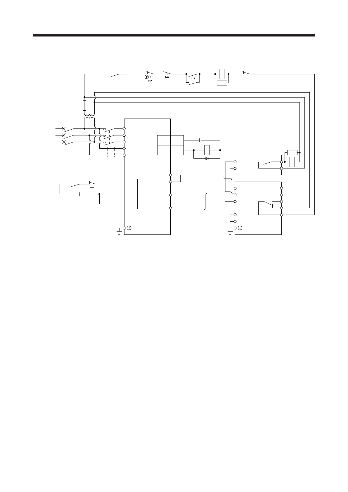
11. OPTIONS AND PERIPHERAL EQUIPMENT
11 - 34
(b) 400 V class
ALM
RA1
OFF RA2
MC
ON
MC
SK
SK
RA2
3
DOCOM
ALM15
CN3
(Note 8)
MC
MCCB
L1
L2
L3
L11
L21
P3
P4
(Note 2)
P+
N-
(Note 6)
(Note 10)
N/-
P/+
BUE
SD
PR
B
C
A
SD
MSG
(Note 3)
(Note 5)
FR-BU2-H
P
PR
TH2
TH1(Note 4)
(Note 7)
RA1
CN3
24 V DC
(Note 11)
5
10
EM2
DICOM
DICOM
20
24 V DC (Note 11)
MT-BR5-H
Step-down
transformer
(Note 1)
Power
supply
Servo amplifier
Emergency stop switch
(Note 9)
Main circuit power supply
Note 1. For power suppl
y
specifications, refer to section 1.3.
2. Between P3 and P4 is connected by default. When using the power factor improving DC reactor, remove the short bar
between P3 and P4. Refer to section 11.11 for details. Additionally, a power factor improving DC reactor and power factor
improvin
g
AC reactor cannot be used simultaneousl
y
.
3. Connect P/+ and N/- terminals of the brake unit to a correct destination. Incorrect connection destination results in servo
amplifier and brake unit malfunction.
4. Contact rating: 1a contact, 110 V AC, 5 A/220 V AC, 3 A
Normal condition: TH1-TH2 is not conductin
g
. Abnormal condition: TH1-TH2 is conductin
g
.
5. Contact rating: 230 V AC, 0.3 A/30 V DC, 0.3 A
Normal condition: B-C is conductin
g
./A-C is not conductin
g
. Abnormal condition: B-C is not conductin
g
./A-C is conductin
g
.
6. Do not connect more than one cable to each P+ and N- terminals of the servo amplifier.
7.
A
lwa
y
s connect BUE and SD terminals.
(
factor
y
-wired
)
8. Depending on the main circuit voltage and operation pattern, bus voltage decreases, and that may cause the forced stop
deceleration to shift to the dynamic brake deceleration. When dynamic brake deceleration is not required, slow the time to turn
off the ma
g
netic contactor.
9. Configure a circuit to turn off EM2 when the main circuit power is turned off to prevent an unexpected restart of the servo
amplifier.
10. When wires used for L11 and L21 are thinner than wires used for L1, L2, and L3, use a molded-case circuit breaker.
11. The illustration of the 24 V DC power supply is divided between input signal and output signal for convenience. However, they
can be confi
g
ured b
y
one.
11. OPTIONS AND PERIPHERAL EQUIPMENT
11 - 35
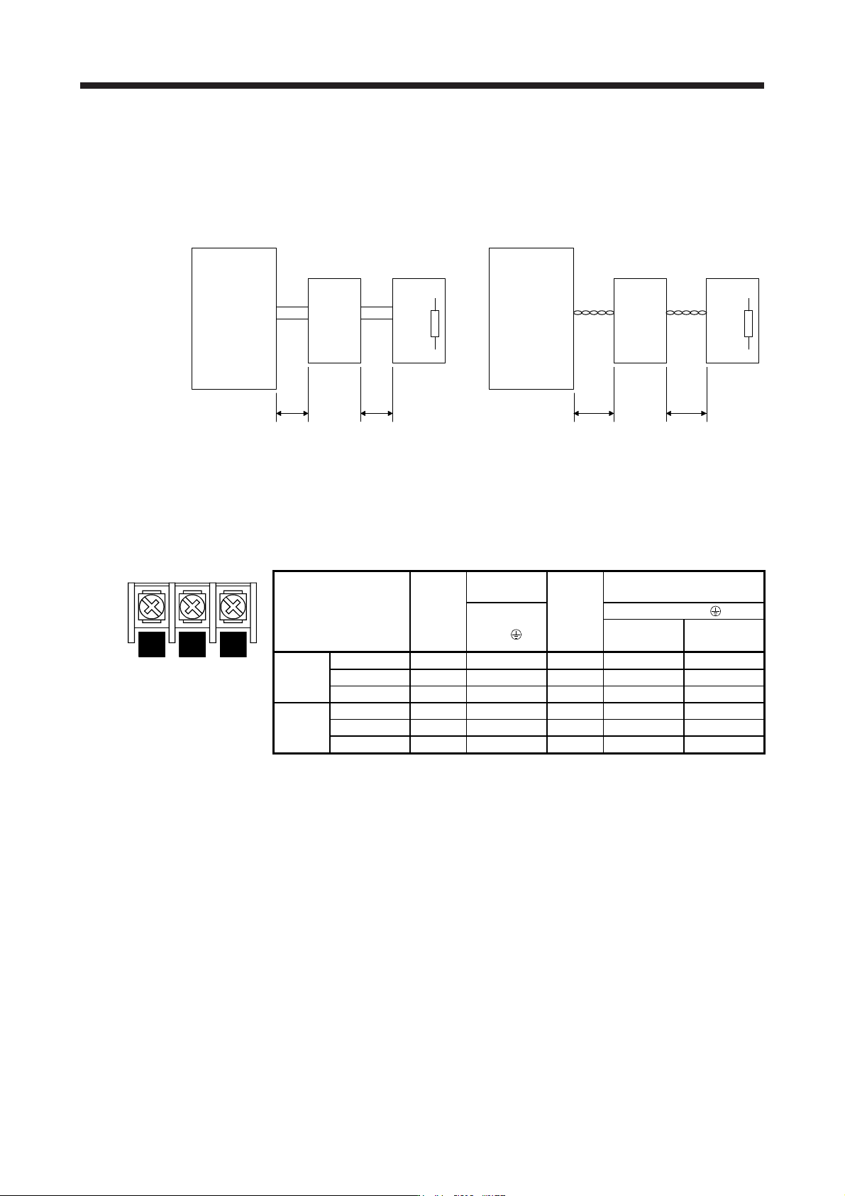
(3) Connection instructions
Keep the wires between the servo amplifier and the brake unit, and between the resistor unit and the
brake unit as short as possible. For wires longer than 5 m, twist the wires five times or more per meter.
The wires should not exceed 10 m even when the wires are twisted. If wires exceeding 5 m without
twisted or exceeding 10 m with or without twisted are used, the brake unit may malfunction.
Servo amplifier
Brake unit
5 m or less 5 m or less
Servo amplifier
Brake unit
10 m or less 10 m or less
P+
N-
P/+
N/-
P
PR
P
PR
P/+
N/-
P
PR
P
PR
Twist Twist
Resistor unit Resistor unit
P+
N-
(4) Wires
(a) Wires for the brake unit
For the brake unit, HIV wire (600 V Grade heat-resistant polyvinyl chloride insulated wire) is
recommended.
1) Main circuit terminal
N/- P/+ PR
Terminal block
Brake unit
Main
circuit
screw
size
Crimp
terminal
Tightening
torque
[N•m]
Wire size
N/-, P/+,
PR,
N/-, P/+, PR,
HIV wire
[mm
2
]
AWG
200 V
class
FR-BU2-15K M4 5.5-4 1.5 3.5 12
FR-BU2-30K M5 5.5-5 2.5 5.5 10
FR-BU2-55K M6 14-6 4.4 14 6
400 V
class
FR-BU2-H30K M4 5.5-4 1.5 3.5 12
FR-BU2-H55K M5 5.5-5 2.5 5.5 10
FR-BU2-H75K M6 14-6 4.4 14 6
11. OPTIONS AND PERIPHERAL EQUIPMENT
11 - 36
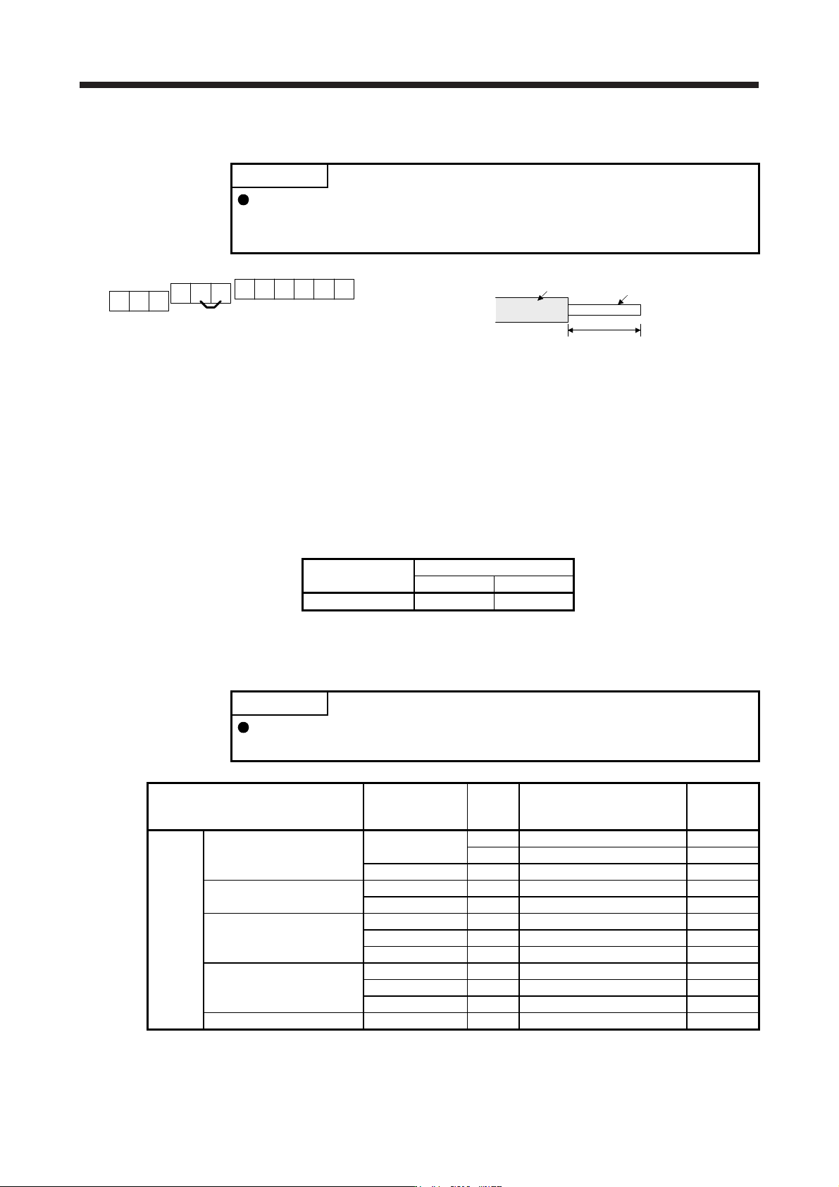
2) Control circuit terminal
POINT
Under tightening can cause a cable disconnection or malfunction. Over
tightening can cause a short circuit or malfunction due to damage to the screw
or the brake unit.
A
RES
PC
B
SD
BUE
C
MSG
SD
MSG
SD SD
Jumper
Terminal block
Insulator
Core
6 mm
Wire the stripped cable after twisting to prevent the cable
from becoming loose. In addition, do not solder it.
Screw size: M3
Tightening torque: 0.5 N•m to 0.6 N•m
Wire size: 0.3 mm
2
to 0.75 mm
2
Screw driver: Small flat-blade screwdriver
(Tip thickness: 0.4 mm/Tip width 2.5 mm)
(b) Cables for connecting the servo amplifier and a distribution terminal block when connecting two sets
of the brake unit
Brake unit
Wire size
HIV wire [mm
2
]AWG
FR-BU2-15K 8 8
(5) Crimp terminals for P+ and N- terminals of servo amplifier
(a) Recommended crimp terminals
POINT
Some crimp terminals may not be mounted depending on the size. Make sure to
use the recommended ones or equivalent ones.
Servo amplifier Brake unit
Number of
connected
units
Crimp terminal (Manufacturer)
(Note 1)
Applicable
tool
200 V
class
MR-J4-500B(-RJ) FR-BU2-15K 1 FVD5.5-S4 (JST) a
2 8-4NS (JST) (Note 2) b
FR-BU2-30K 1 FVD5.5-S4 (JST) a
MR-J4-700B(-RJ) FR-BU2-15K 2 8-4NS (JST) (Note 2) b
FR-BU2-30K 1 FVD5.5-S4 (JST) a
MR-J4-11KB(-RJ) FR-BU2-15K 2 FVD8-6 (JST) c
FR-BU2-30K 1 FVD5.5-6 (JST) a
FR-BU2-55K 1 FVD14-6 (JST) d
MR-J4-15KB(-RJ) FR-BU2-15K 2 FVD8-6 (JST) c
FR-BU2-30K 1 FVD5.5-6 (JST) a
FR-BU2-55K 1 FVD14-6 (JST) d
MR-J4-22KB(-RJ) FR-BU2-55K 1 FVD14-8 (JST) d