sh030106u.pdf - 第137页
4. STA RTUP 4 - 12 4.3.3 St atus dis play of a n axis (1) Display sequenc e The segment of the last 2 digits shows the axis number. Servo system controller power on (SSCNET III/H communication begins) Ready-on Servo-on O…
4. STARTUP
4 - 11
4.3.2 Scrolling display
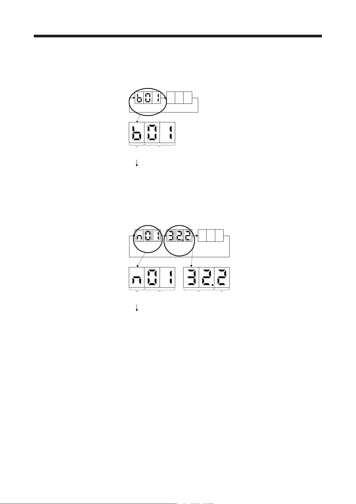
(1) Normal display
When there is no alarm, the axis No. and blank are displayed in rotation.
Status
(1 digit)
Axis No.
(2 digits)
"b"
"C"
"d"
: Indicates ready-off and servo-off status.
: Indicates ready-on and servo-off status.
: Indicates ready-on and servo-on status.
Status
A
fter 1.6 s
Blank
After 0.2 s
(2) Alarm display
When an alarm occurs, the alarm number (two digits) and the alarm detail (one digit) are displayed
following the status display. For example, the following shows when [AL. 32 Overcurrent] is occurring.
Status
After 0.8 s
Alarm No.
After 0.8 s
Blank
After 0.2 s
Status
(1 digit)
Axis No.
(2 digits)
"n": Indicates that an alarm is occurring.
Alarm detail
(1 digit)
Alarm No.
(2 digits)
4. STARTUP
4 - 12
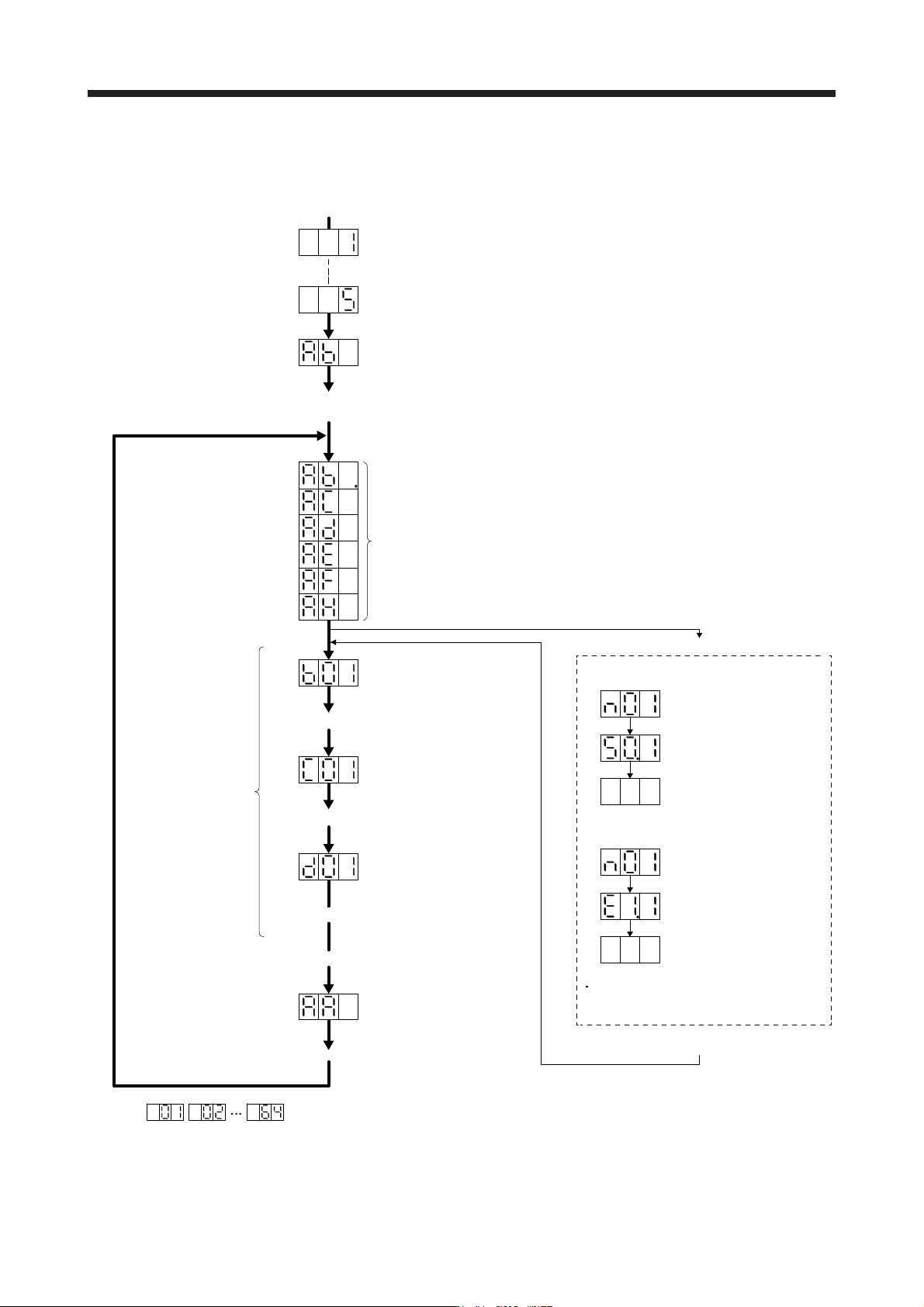
4.3.3 Status display of an axis
(1) Display sequence
The segment of the last 2 digits shows the axis number.
Servo system controller power on
(SSCNET III/H communication begins)
Ready-on
Servo-on
Ordinary operation
Servo system controller power off
Servo system controller power on
When an alarm or a
warning occurs, the
alarm No. or the
warning No. is shown.
Waiting for servo system controller power to switch on
(SSCNET III/H communication)
Ready-on and servo-off
Ready-on and servo-on
(Note)
(Note)
(Note)
When an alarm No. or warning No. is displayed
Axis
No. 1
Axis
No. 2
Axis
No. 64
Initial data communication with the
servo system controller
(initialization communication)
Ready-off and servo-off
Note.
Example:
Blinking
Blinking
After 0.8 s
Blank
After 0.8 s
When [AL. 50 Overload 1]
occurs at axis No. 1
Example:
Blinking
Blinking
After 0.8 s
Blank
After 0.8 s
When [AL. E1 Overload warning 1]
occurs at axis No. 1
During a warning that does not cause
servo-off, the decimal point on the third
digit LED shows the servo-on status.
Servo amplifier power on
System check in progress
Alarm reset or warning cleared
4. STARTUP
4 - 13
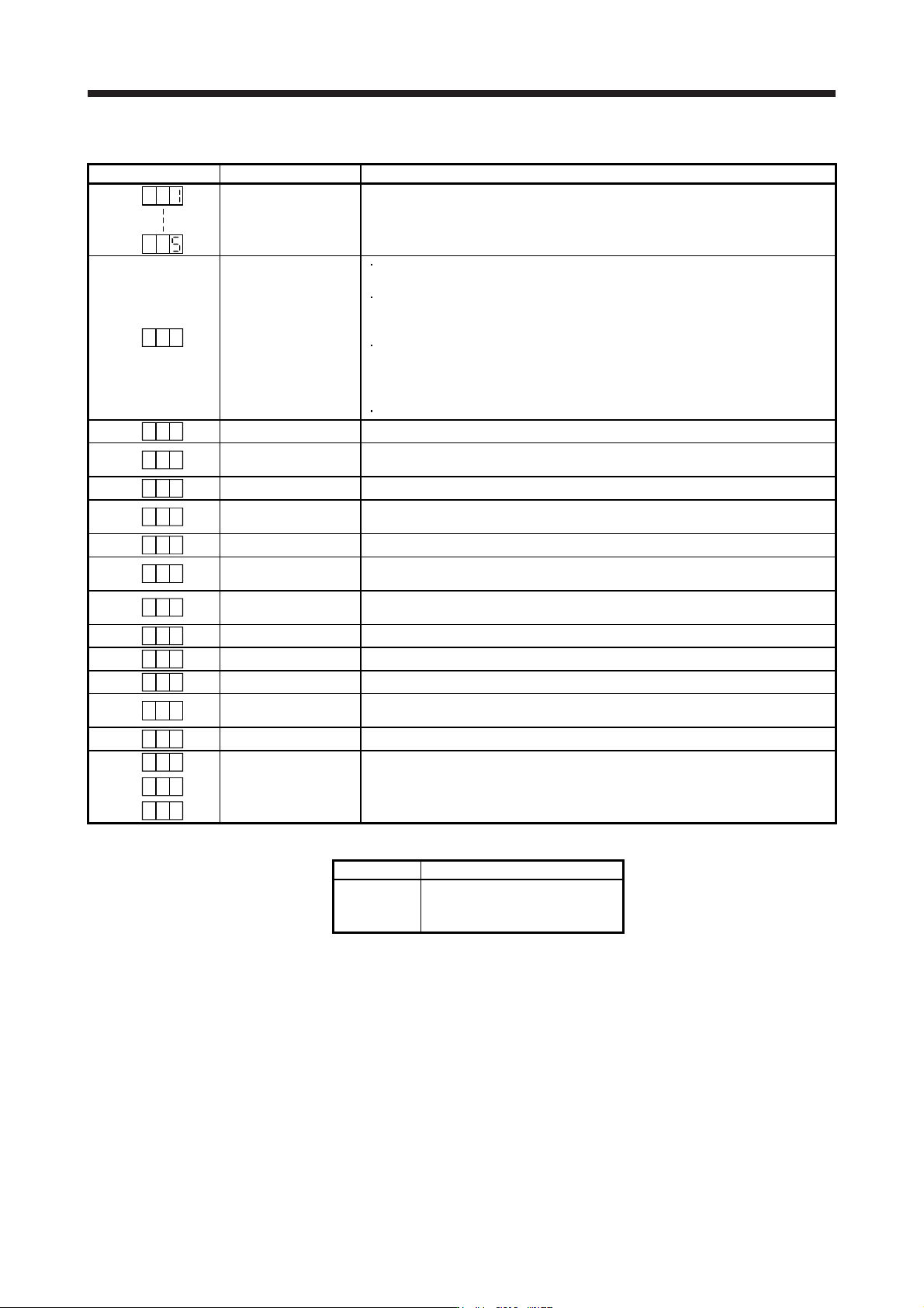
(2) Indication list
Indication Status Description
Initializing System check in progress
A b
Initializing
Power of the servo amplifier was switched on at the condition that the power of the
servo system controller is off.
The control axis No. set to the auxiliary axis number setting switches (SW2-3 and
SW2-4) and the axis selection rotary switch (SW1) do not match the one set to the
servo system controller.
A servo amplifier malfunctioned, or communication error occurred with the servo
system controller or the previous axis servo amplifier. In this case, the indication
changes as follows:
"Ab", "AC", "Ad", and "Ab"
The servo system controller is malfunctioning.
A b .
Initializing During initial setting for communication specifications
A C
Initializing
Initial setting for communication specifications completed, and then it synchronized
with servo system controller.
A d
Initializing During initial parameter setting communication with servo system controller
A E
Initializing
During the servo motor/encoder information and telecommunication with servo
system controller
A F
Initializing During initial signal data communication with servo system controller
A H
Initializing completion
The process for initial data communication with the servo system controller is
completed.
A A
Initializing standby
The power supply of servo system controller is turned off during the power supply of
servo amplifier is on.
(Note 1)
b
# #
Ready-off The ready-off signal from the servo system controller was received.
(Note 1)
d
# #
Servo-on The ready-off signal from the servo system controller was received.
(Note 1)
C
# #
Servo-off The ready-off signal from the servo system controller was received.
(Note 2)
* **
Alarm and warning
The alarm No. and the warning No. that occurred is displayed. (Refer to section 8.
(Note 4))
8 88
CPU error CPU watchdog error has occurred.
(Note 1)
# #b.
(Note 3)
Test operation mode
JOG operation, positioning operation, program operation, output signal (DO) forced
output, or motor-less operation was set.
# #d.
# #C.
Note 1. The meanin
g
s of ## are listed below.
## Description
01
to
64
Axis No. 1
to
Axis No. 64
2. ** indicates the alarm No. and the warnin
g
No.
3. Requires the MR Confi
g
urator2.
4. Only a list of alarms and warnings is listed in chapter 8. Refer to "MELSERVO-J4 Servo Amplifier Instruction Manual
(
Troubleshootin
g)
" for details of alarms and warnin
g
s.