sh030106u.pdf - 第301页
9. DIMENSIONS 9 - 18 (3) 100 V clas s (a) MR-J4-10B1(-RJ)/MR-J4-2 0B1(-RJ) [Unit: mm] 156 6 6 40 6 6 135 4 168 161 PE CNP1 CNP2 CNP3 Approx. 80 Approx. 69.3 Approx . 21 Wit h MR-BAT6V1 SET Lock knob Approx. 38.5 Mass : 0…
9. DIMENSIONS
9 - 17
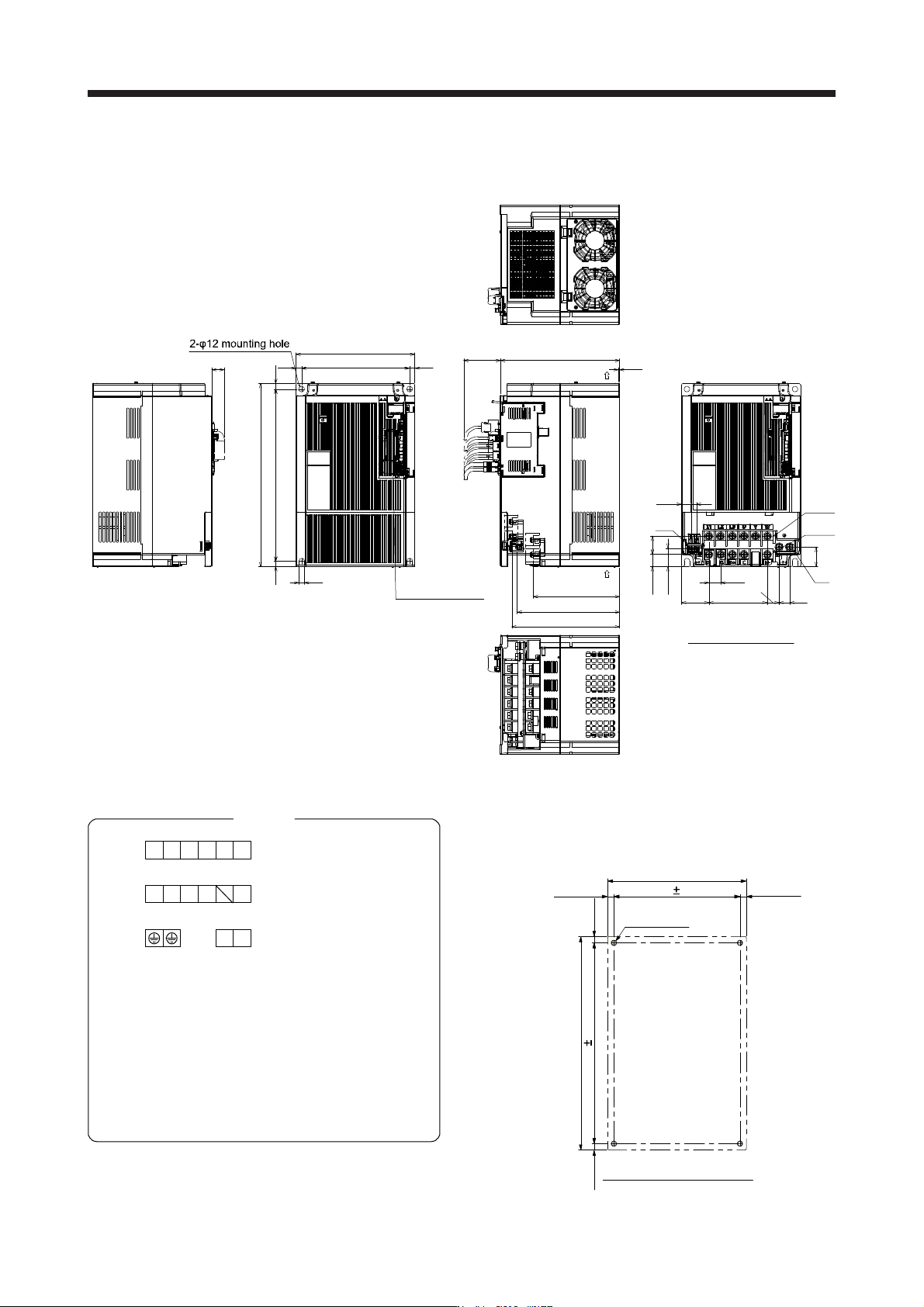
(g) MR-J4-22KB4(-RJ)
[Unit: mm]
260
400
12 12
12
236
260
2.3
188.5
223.4
235.4
37612
12
PE
5 × 25.5 (= 127.5)
40.5
4026.5
25.9
11
TE1-2
TE1-1
TE2
59.9
25.5
21.7
43
23
Terminal block layout
Intake
Cooling fan exhaust
Approx. 80
Approx. 28
With
MR-BAT6V1 SET
Mass: 18.2 [kg]
TE1-2
TE2
Screw size: M8
Tightening torque: 6.0 [N•m]
Screw size: M4
Tightening torque: 1.2 [N•m]
PE
TE1-1
PE
Screw size: M8
Tightening torque: 6.0 [N•m]
Screw size: M8
Tightening torque: 6.0 [N•m]
TE1-1
TE1-2
TE2
Terminal
L1 L2 L3 VW
CN-P4 P+
U
P3
L11 L21
Mounting screw
Screw size: M10
Tightening torque: 26.5 [N•m]
376 0.5
Mounting hole location diagram
Approx.
12
Approx. 400
0.5
Approx. 12
A
pprox. 1
2
236
4-M10 screw
Approx.
12
Approx. 26
0
9. DIMENSIONS
9 - 18
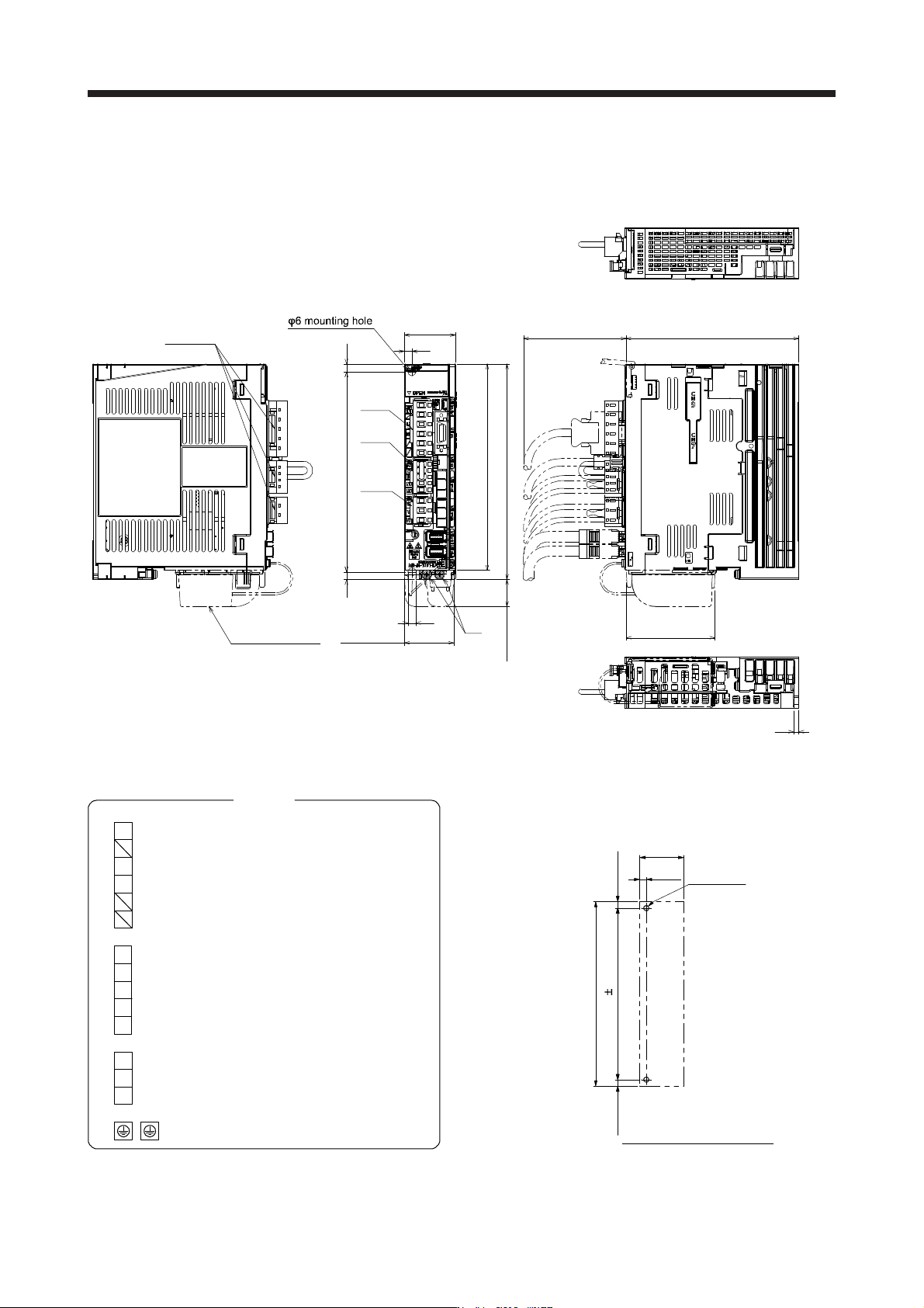
(3) 100 V class
(a) MR-J4-10B1(-RJ)/MR-J4-20B1(-RJ)
[Unit: mm]
1566
6
40
6
6
135
4
168
161
PE
CNP1
CNP2
CNP3
Approx. 80
Approx. 69.3
Approx. 21
With
MR-BAT6V1 SET
Lock knob
Approx. 38.5
Mass: 0.8 [kg]
PE
Terminal
Screw size: M4
Tightening torque: 1.2 [N•m]
N-
L11
L21
L2
L1
C
D
P+
CNP1
CNP2
V
W
U
CNP3
Mounting screw
Screw size: M5
Tightening torque: 3.24 [N•m]
156 0.5
2-M5 screw
Approx. 40
Approx.
6
Approx. 6
Approx. 168
Approx. 6
Mounting hole location diagram
9. DIMENSIONS
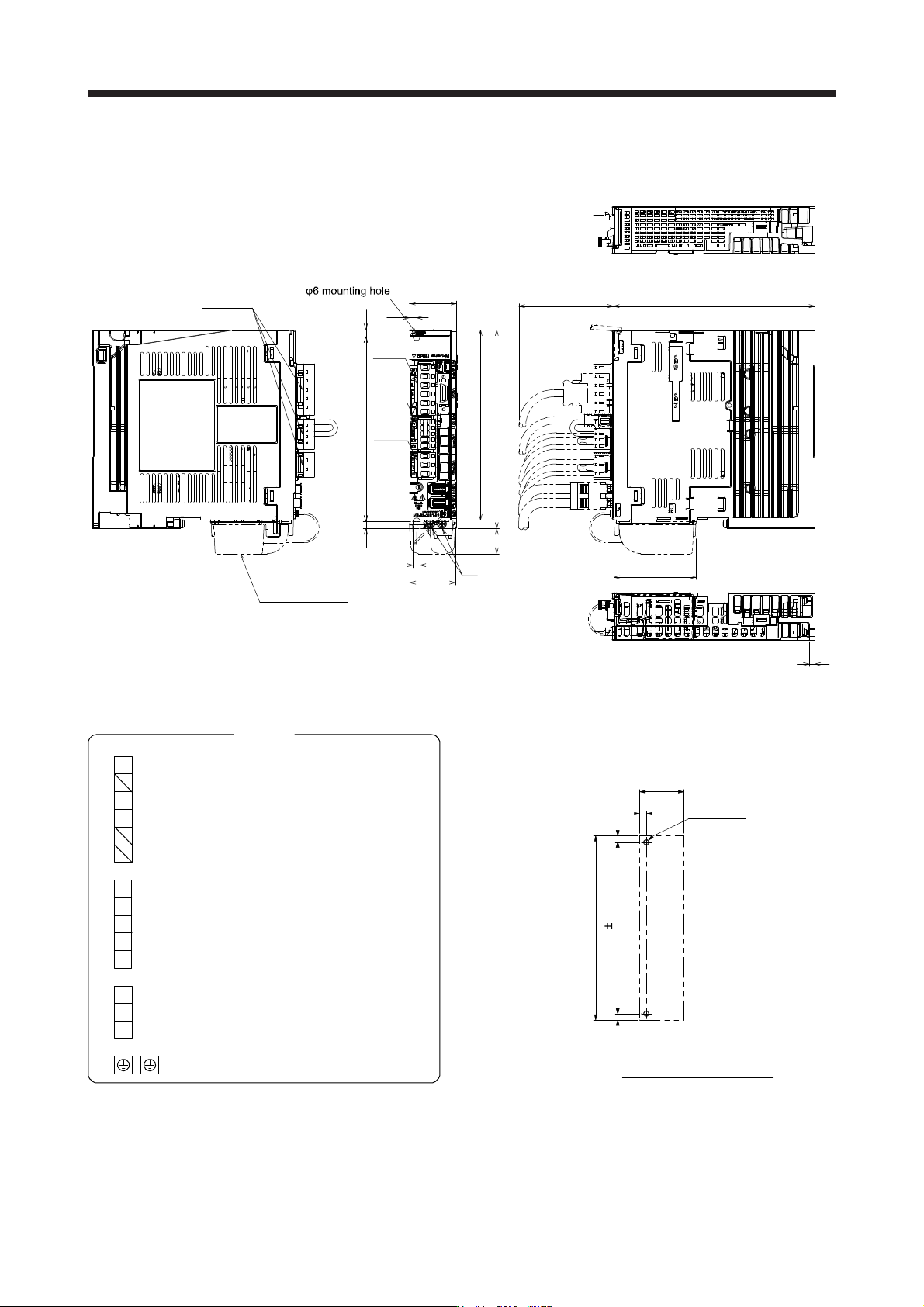
9 - 19
(b) MR-J4-40B1(-RJ)
[Unit: mm]
170
156
161
168
6
40
6
6
5
6
PE
CNP1
CNP2
CNP3
Lock knob
With
MR-BAT6V1 SET
Approx. 21
Approx. 38.5
Approx. 69.3
Approx. 80
Mass: 1.0 [kg]
PE
Terminal
Screw size: M4
Tightening torque: 1.2 [N•m]
N-
L11
L21
L2
L1
C
D
P+
CNP1
CNP2
V
W
U
CNP3
Mounting screw
Screw size: M5
Tightening torque: 3.24 [N•m]
156 0.5
2-M5 screw
Approx. 40
Approx.
6
Approx. 6
Approx. 168
Approx. 6
Mounting hole location diagram