sh030106u.pdf - 第229页
6. NORM AL GAIN ADJ USTMENT 6 - 28 MEMO

6. NORMAL GAIN ADJUSTMENT
6 - 27
(4) Parameter adjustment
[Pr. PB07 Model loop gain]
This parameter determines the response level of the position control loop. Increasing the value improves
trackability to a position command, but a too high value will make overshoot liable to occur at settling.
Number of droop pulses is determined by the following expression.
Number of droop pulses [pulse] =
Model loop gain setting
Position command frequency [pulse/s]
Position command frequency differs depending on the operation mode.
Rotary servo motor and direct drive motor:
Position command frequency
=
Speed [r/min]
60
× Encoder resolution (number of pulses per servo motor revolution)
Linear servo motor:
Position command frequency = Speed [mm/s] ÷ Encoder resolution (travel distance per pulse)

6. NORMAL GAIN ADJUSTMENT
6 - 28
MEMO
7. SPECIAL ADJUSTMENT FUNCTIONS
7 - 1
7. SPECIAL ADJUSTMENT FUNCTIONS
POINT
The functions given in this chapter need not be used normally. Use them if you
are not satisfied with the machine status after making adjustment in the methods
in chapter 6.
When you use a linear servo motor, replace the following words in the left to the
words in the right.
Load to motor inertia ratio → Load to motor mass ratio
Torque → Thrust
(Servo motor) speed → (Linear servo motor) speed
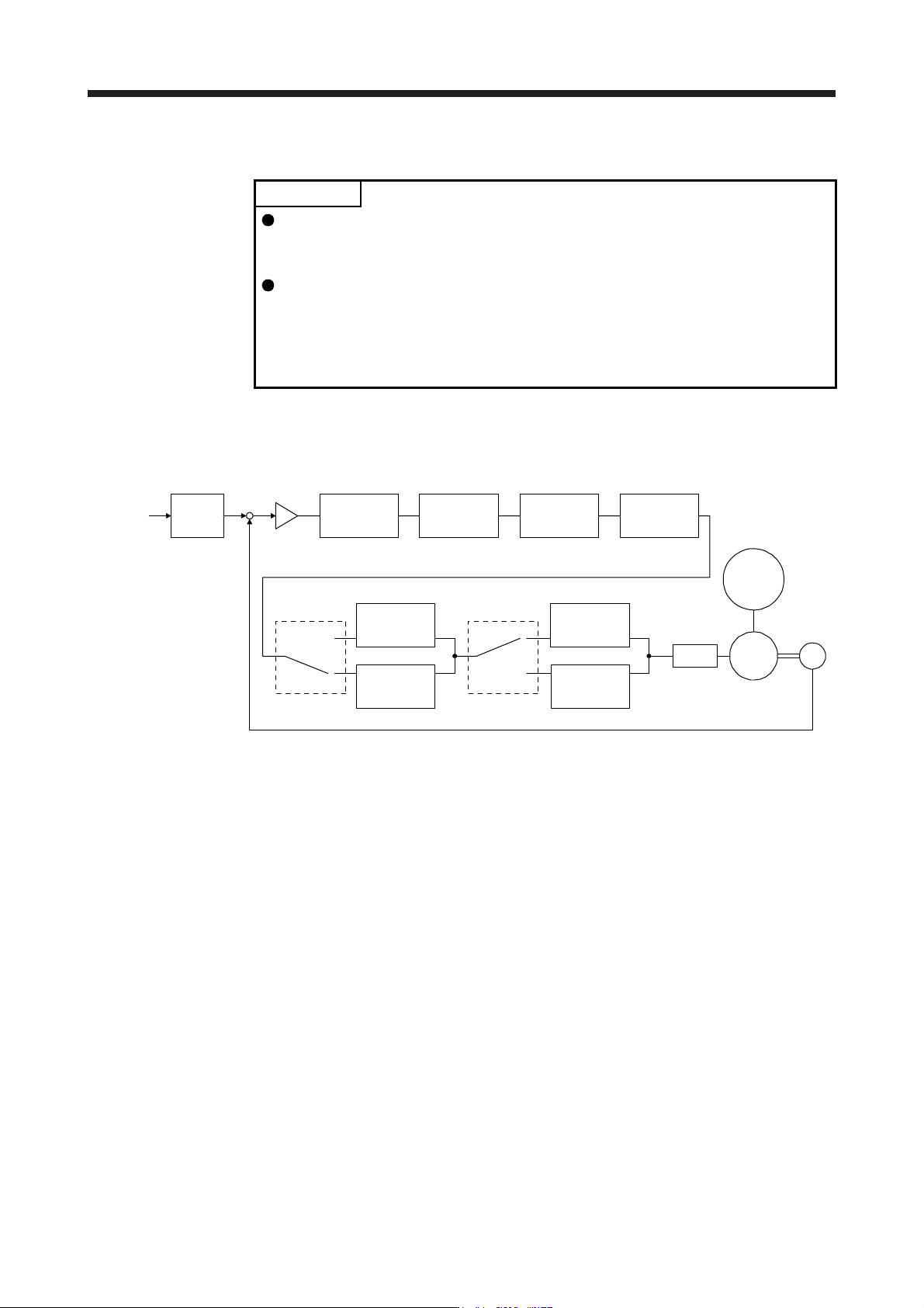
7.1 Filter setting
The following filters are available with MR-J4 servo amplifiers.
Command
pulse train
Command
filter
Low-pass
filter
setting
Encoder
Servo motor
PWM
M
Load
[Pr. PB18]
+
-
Machine
resonance
suppression
filter 1
[Pr. PB13] [Pr. PB15] [Pr. PB46]
Machine
resonance
suppression
filter 2
Machine
resonance
suppression
filter 3
Machine
resonance
suppression
filter 4
Machine
resonance
suppression
filter 5
Shaft
resonance
suppression
filter
Robust filter
[Pr. PB48]
[Pr. PB50]
[Pr. PB17]
Speed
control
[Pr. PB49] [Pr. PE41]