sh030106u.pdf - 第55页
1. FUNCTI ONS AND CONF IGURATION 1 - 38 (2) Reinstal lation of t he fro nt cov er Fr ont cover setting tab A) A) 1) Ins ert the front c over setting tabs i nto the sockets of servo ampl ifier (2 pl ace s). 2) Push down t…
1. FUNCTIONS AND CONFIGURATION
1 - 37
1.7.2 Removal and reinstallation of the front cover
WARNING
Before removing or installing the front cover, turn off the power and wait for 15
minutes or more until the charge lamp turns off. Then, confirm that the voltage
between P+ and N- is safe with a voltage tester and others. Otherwise, an electric
shock may occur. In addition, when confirming whether the charge lamp is off or
not, always confirm it from the front of the servo amplifier.
The following shows how to remove and reinstall the front cover of MR-J4-700B(-RJ) to MR-J4-22KB(-RJ)
and MR-J4-500B4(-RJ) to MR-J4-22KB4(-RJ).
The diagram is for MR-J4-700B.
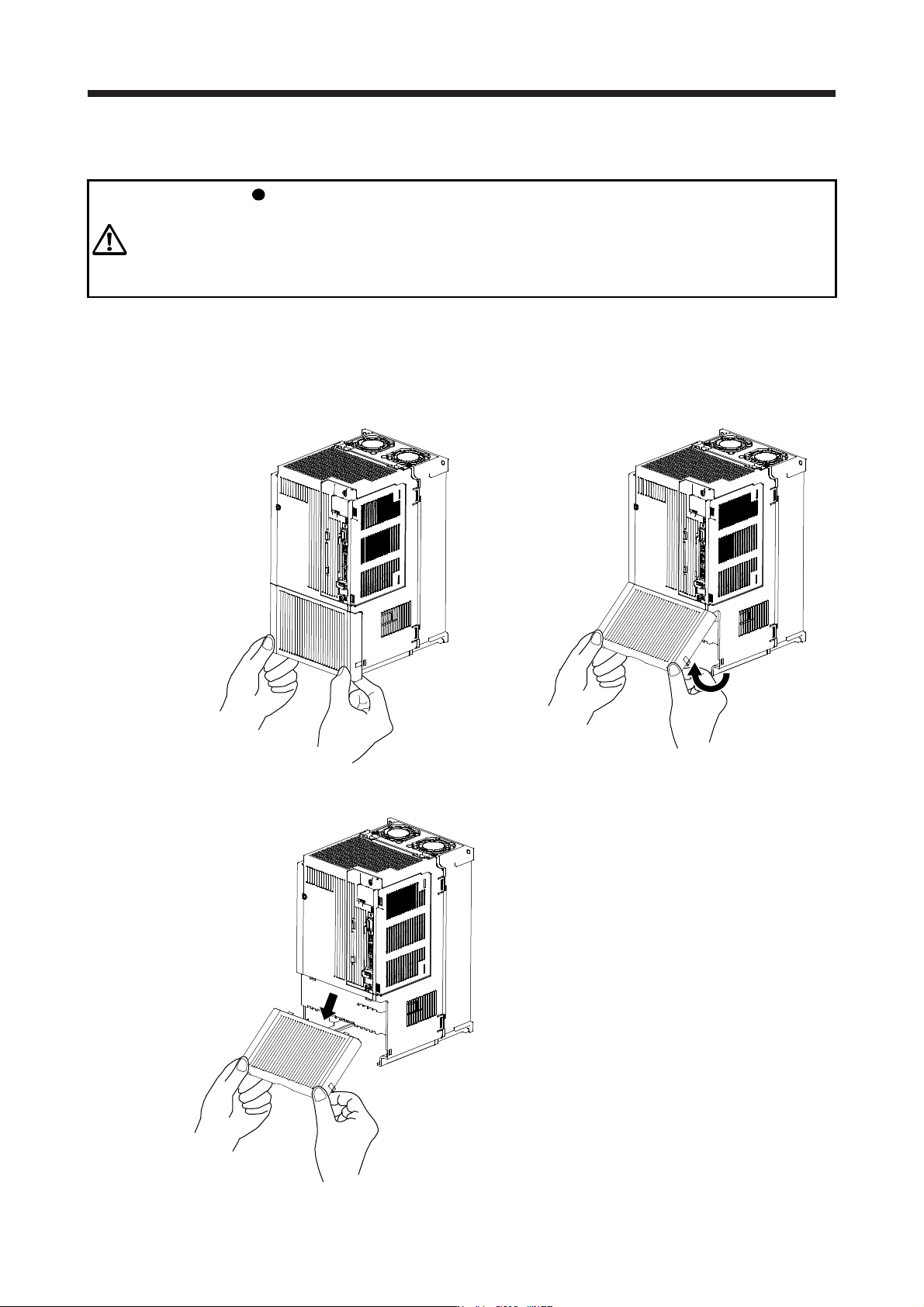
(1) Removal of the front cover
A)
A)
1) Hold the ends of lower side of the front cover with
both hands.
2) Pull up the cover, supporting at point A).
3) Pull out the front cover to remove.
1. FUNCTIONS AND CONFIGURATION
1 - 38
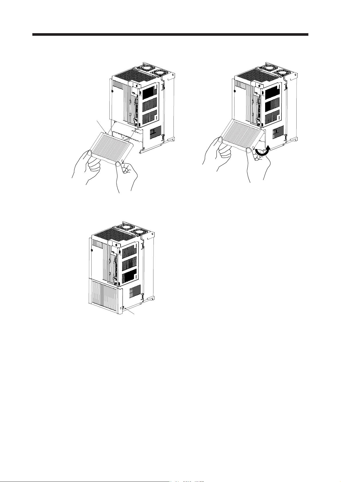
(2) Reinstallation of the front cover
Front cover
setting tab
A)
A)
1) Insert the front cover setting tabs into the sockets of
servo amplifier (2 places).
2) Push down the cover, supporting at point A).
Setting tab
3) Press the cover against the terminal box until the
installing knobs click.
1. FUNCTIONS AND CONFIGURATION
1 - 39
1.8 Configuration including peripheral equipment
CAUTION
Connecting a servo motor of the wrong axis to U, V, W, or CN2 of the servo
amplifier may cause a malfunction.
POINT
Equipment other than the servo amplifier and servo motor are optional or
recommended products.
When using the MR-J4-_B-RJ servo amplifier with the DC power supply input,
refer to app. 15.