sh030106u.pdf - 第32页
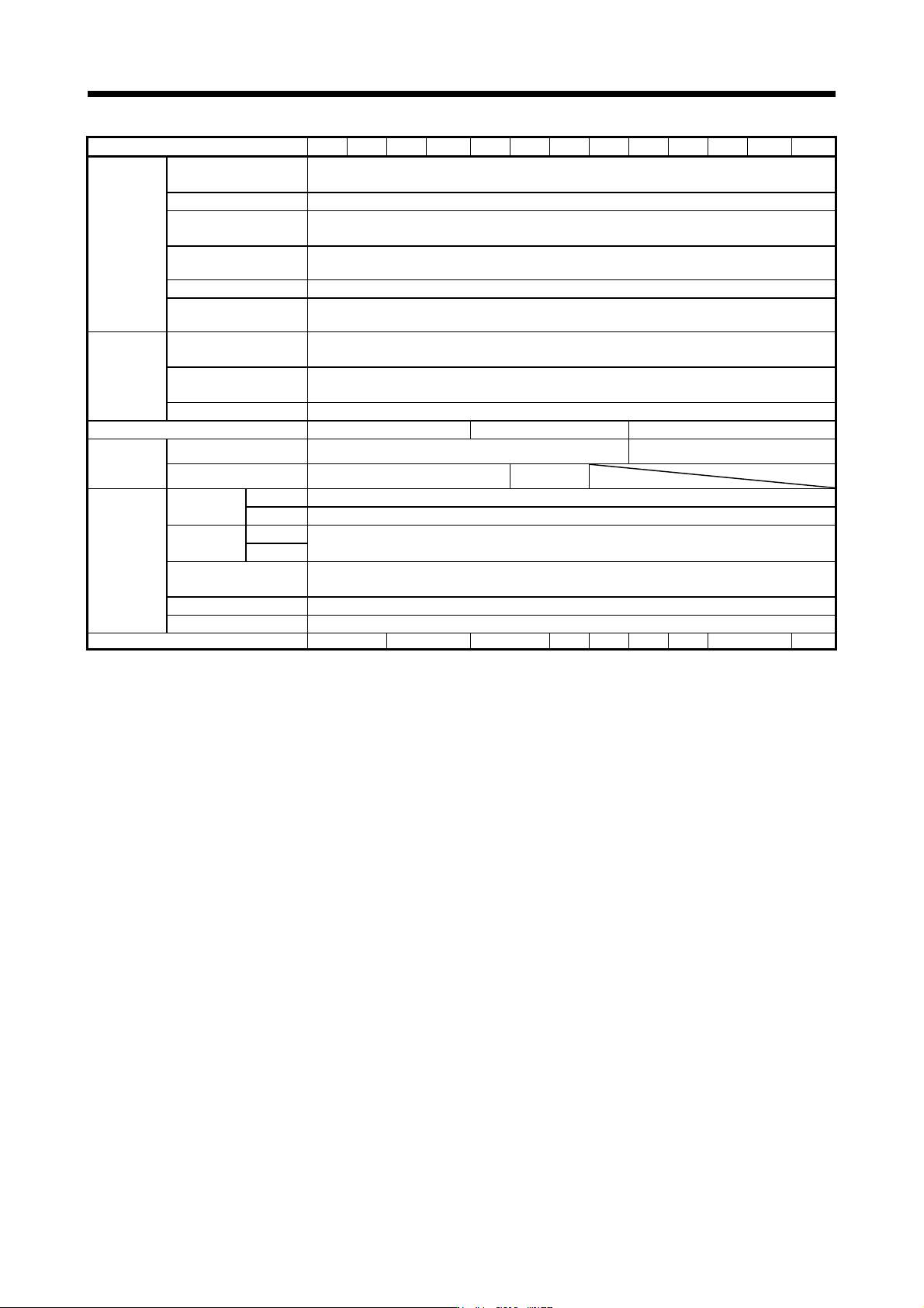
1. FUNCTIONS AND CONFIGURATION 1 - 15 (2) 400 V class Model: MR-J4-_(-RJ) 60B4 100B4 200B4 350B4 500B4 700B4 11KB4 15KB4 22KB4 Output Rated voltage 3-phase 323 V AC Rated current [A] 1.5 2.8 5. 4 8.6 14.0 17.0 32.0 41.0 …
1. FUNCTIONS AND CONFIGURATION
1 - 14
Model: MR-J4-_(-RJ) 10B 20B 40B 60B 70B 100B 200B 350B 500B 700B 11KB 15KB 22KB
Safety
performance
Standards (Note 14)
EN ISO 13849-1:2015 Category 3 PL e, IEC 61508 SIL 3,
EN IEC 62061 maximum SIL 3, EN 61800-5-2
Response performance 8 ms or less (STO input off → energy shut off)
Test pulse input (STO)
(Note 3)
Test pulse interval: 1 Hz to 25 Hz
Test pulse off time: Up to 1 ms
Mean time to dangerous
failure (MTTFd)
MTTFd ≥ 100 [years] (314a)
Diagnostic coverage (DC) DC = Medium, 97.6 [%]
Probability of dangerous
failures per hour (PFH)
PFH = 6.4 × 10
-9
[1/h]
Global
standards
CE marking
LVD: EN 61800-5-1, EMC: EN 61800-3,
MD: EN ISO 13849-1:2015, EN 61800-5-2, EN IEC 62061
UKCA marking
LVD: BS EN 61800-5-1, EMC: BS EN IEC 61800-3,
MD: BS EN ISO 13849-1:2015, BS EN 61800-5-2, BS EN IEC 62061
UL standard UL 61800-5-1
Structure (IP rating) Natural cooling, open (IP20) Force cooling, open (IP20) Force cooling, open (IP20) (Note 4)
Close
mounting
(Note 2)
3-phase power supply input Possible Impossible
1-phase power supply input Possible Impossible
Environment
Ambient
temperature
Operation 0 ˚C to 55 ˚C (non-freezing)
Storage -20 ˚C to 65 ˚C (non-freezing)
Ambient
humidity
Operation
5 %RH to 90 %RH (non-condensing)
Storage
Ambience
Indoors (no direct sunlight),
free from corrosive gas, flammable gas, oil mist, dust, and dirt
Altitude 2000 m or less above sea level (Note 15)
Vibration resistance 5.9 m/s
2
, at 10 Hz to 55 Hz (directions of X, Y and Z axes)
Mass [kg] 0.8 1.0 1.4 2.1 2.3 4.0 6.2 13.4 18.2
Note 1. 0.3 A is the value applicable when all I/O signals are used. The current capacity can be decreased by reducing the number of
I/O points.
2. When closely mounting the servo amplifiers, operate them at the ambient temperature of 0 ˚C to 45 ˚C or at 75% or smaller
effective load ratio.
3. Test pulse is a signal which instantaneously turns off a signal to the servo amplifier at a constant period for external circuit to
self-diagnose.
4. Except for the terminal block.
5. MR-J4-_B servo amplifier is compatible only with two-wire type. MR-J4-_B-RJ servo amplifier is compatible with two-wire type,
four-wire type, and A/B/Z-phase differential output method. Refer to table 1.1 for details.
6 The rated current is 2.9 A when the servo amplifier is used with the 3-phase power supply and a UL or CSA compliant servo
motor.
7. For the compatible version of fully closed loop system, refer to table 1.1.
8. The communication cycle depends on the controller specifications and the number of axes connected.
9. Use an external dynamic brake for this servo amplifier. Failure to do so will cause an accident because the servo motor does
not stop immediately but coasts at emergency stop. Ensure the safety in the entire equipment.
10. For the compatible version for the scale measurement function, refer to table 1.1.
11. The value in ( ) is the rated current for the 1-phase power supply input.
12. The external dynamic brake cannot be used for compliance with SEMI-F47 standard. Do not assign DB (Dynamic brake
interlock) in [Pr. PD07] to [Pr. PD09]. Failure to do so will cause the servo amplifier to become servo-off when an
instantaneous power failure occurs.
13. When using 1-phase 200 V AC to 240 V AC power supply, operate the servo amplifier at 75% or smaller effective load ratio.
14. The safety level depends on the setting value of [Pr. PF18 STO diagnosis error detection time] and whether STO input
diagnosis by TOFB output is performed or not. For details, refer to the Function column of [Pr. PF18] in section 5.2.6.
15. Follow the restrictions in section 2.7 when using this product at altitude exceeding 1000 m and up to 2000 m above sea level.
16. The DC power supply input is available only with MR-J4-_B-RJ servo amplifiers. For parameter setting values when a DC
input is used, refer to the Function column of [Pr. PC20] in section 5.2.3. For the connection example of the power circuit, refer
to app. 16.
1. FUNCTIONS AND CONFIGURATION
1 - 15
(2) 400 V class
Model: MR-J4-_(-RJ) 60B4 100B4 200B4 350B4 500B4 700B4 11KB4 15KB4 22KB4
Output
Rated voltage 3-phase 323 V AC
Rated current [A] 1.5 2.8 5.4 8.6 14.0 17.0 32.0 41.0 63.0
Main circuit
power supply
input
Voltage/Frequency 3-phase 380 V AC to 480 V AC, 50 Hz/60 Hz
Rated current [A] 1.4 2.5 5.1 7.9 10.8 14.4 23.1 31.8 47.6
Permissible voltage
fluctuation
3-phase 323 V AC to 528 V AC
Permissible frequency
fluctuation
Within ±5%
Power supply capacity
[kVA]
Refer to section 10.2.
Inrush current [A] Refer to section 10.5.
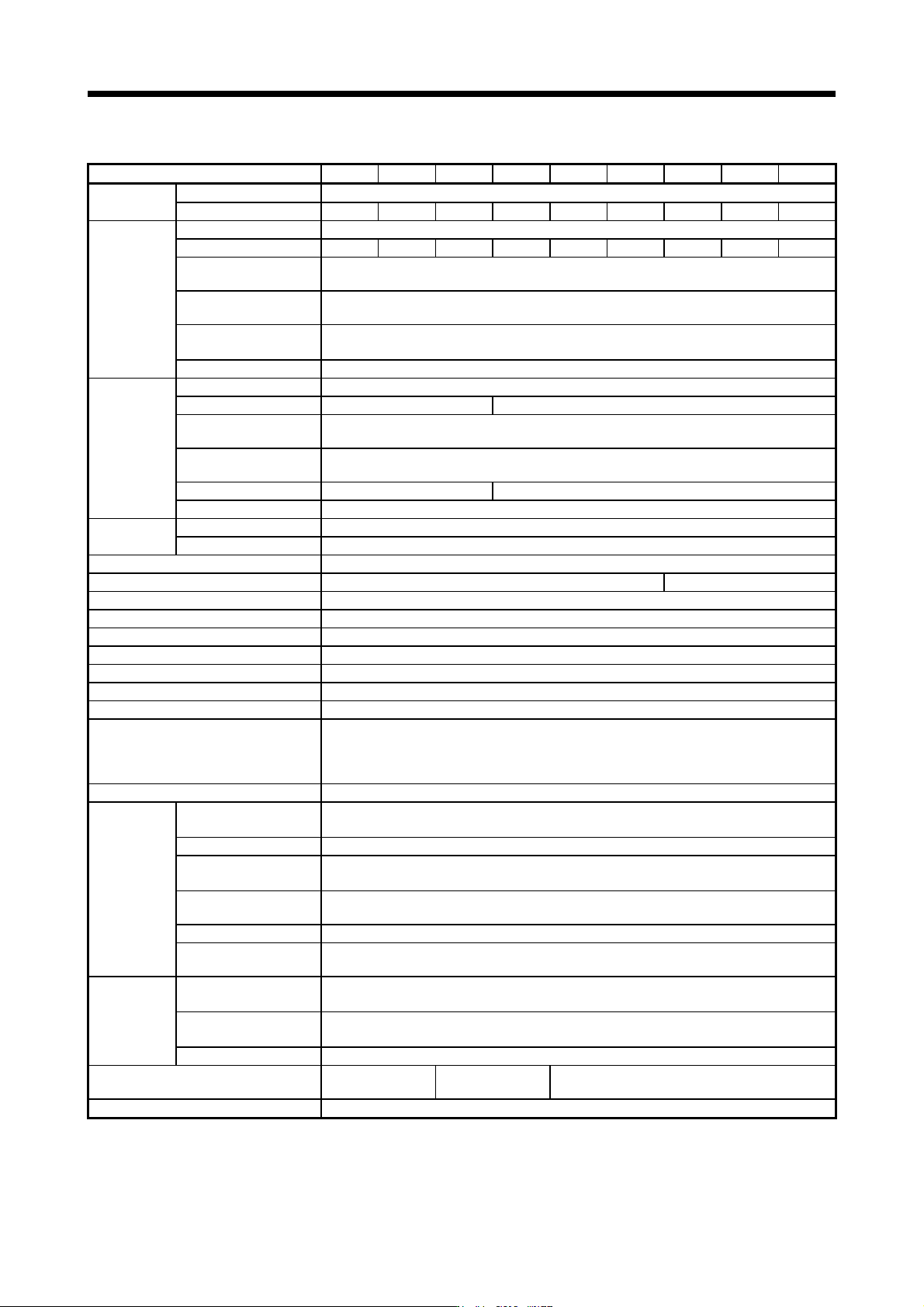
Voltage/Frequency 1-phase 380 V AC to 480 V AC, 50 Hz/60 Hz
Rated current [A] 0.1 0.2
Control circuit
power supply
input
Permissible voltage
fluctuation
1-phase 323 V AC to 528 V AC
Permissible frequency
fluctuation
Within ±5%
Power consumption [W] 30 45
Inrush current [A] Refer to section 10.5.
Interface power
supply
Voltage 24 V DC ± 10%
Current capacity [A] 0.3 (including CN8 connector signals) (Note 1)
Control method Sine-wave PWM control, current control method
Dynamic brake Built-in External option (Note 6, 8)
SSCNET III/H communication cycle (Note 5) 0.222 ms, 0.444 ms, 0.888 ms
Fully closed loop control Compatible
Scale measurement function Compatible (Note 7)
Load-side encoder interface (Note 4) Mitsubishi Electric high-speed serial communication
Communication function USB: connection to a personal computer or others (MR Configurator2-compatible)
Encoder output pulses Compatible (A/B/Z-phase pulse)
Analog monitor Two channels
Protective functions
Overcurrent shut-off, regenerative overvoltage shut-off, overload shut-off (electronic thermal), servo
motor overheat protection, encoder error protection, regenerative error protection, undervoltage
protection, instantaneous power failure protection, overspeed protection, error excessive protection,
magnetic pole detection protection, and linear servo control fault protection
Functional safety STO (IEC/EN 61800-5-2)
Safety
performance
Standards (Note 9)
EN ISO 13849-1:2015 Category 3 PL e, IEC 61508 SIL 3,
EN IEC 62061 maximum SIL 3, EN 61800-5-2
Response performance 8 ms or less (STO input off → energy shut off)
Test pulse input (STO)
(Note 2)
Test pulse interval: 1 Hz to 25 Hz
Test pulse off time: Up to 1 ms
Mean time to dangerous
failure (MTTFd)
MTTFd ≥ 100 [years] (314a)
Diagnosis converge (DC) DC = Medium, 97.6 [%]
Probability of dangerous
failures per hour (PFH)
PFH = 6.4 × 10
-9
[1/h]
Global
standards
CE marking
LVD: EN 61800-5-1, EMC: EN 61800-3, MD: EN ISO 13849-1:2015, EN 61800-5-2,
EN IEC 62061
UKCA marking
LVD: BS EN 61800-5-1, EMC: BS EN IEC 61800-3, MD: BS EN ISO 13849-1:2015,
BS EN 61800-5-2, BS EN IEC 62061
UL standard UL 61800-5-1
Structure (IP rating)
Natural cooling, open
(IP20)
Force cooling, open
(IP20)
Force cooling, open (IP20) (Note 3)
Close mounting Impossible

1. FUNCTIONS AND CONFIGURATION
1 - 16
Model: MR-J4-_(-RJ) 60B4 100B4 200B4 350B4 500B4 700B4 11KB4 15KB4 22KB4
Environment
Ambient
temperature
Operation 0 ˚C to 55 ˚C (non-freezing)
Storage -20 ˚C to 65 ˚C (non-freezing)
Ambient
humidity
Operation
5 %RH to 90 %RH (non-condensing)
Storage
Ambience
Indoors (no direct sunlight),
free from corrosive gas, flammable gas, oil mist, dust, and dirt
Altitude 2000 m or less above sea level (Note 10)
Vibration resistance 5.9 m/s
2
, at 10 Hz to 55 Hz (directions of X, Y and Z axes)
Mass [kg] 1.7 2.1 3.6 4.3 6.5 13.4 18.2
Note 1. 0.3 A is the value applicable when all I/O signals are used. The current capacity can be decreased by reducing the number of
I/O points.
2. Test pulse is a signal which instantaneously turns off a signal to the servo amplifier at a constant period for external circuit to
self-dia
g
nose.
3. Except for the terminal block.
4. MR-J4-B4 servo amplifier is compatible only with two-wire type. MR-J4-B4-RJ servo amplifier is compatible with two-wire type,
fou
r
-wire t
y
pe, and A/B/Z-phase differential output method. Refer to table 1.1 for details.
5. The communication c
y
cle depends on the controller specifications and the number of axes connected.
6. Use an external dynamic brake for this servo amplifier. Failure to do so will cause an accident because the servo motor does
not stop immediatel
y
but coasts at emer
g
enc
y
stop. Ensure the safet
y
in the entire equipment.
7. For the compatible version for the scale measurement function, refer to table 1.1.
8. The external dynamic brake cannot be used for compliance with SEMI-F47 standard. Do not assign DB (Dynamic brake
interlock) in [Pr. PD07] to [Pr. PD09]. Failure to do so will cause the servo amplifier to become servo-off when an
instantaneous power failure occurs.
9. The safety level depends on the setting value of [Pr. PF18 STO diagnosis error detection time] and whether STO input
dia
g
nosis b
y
TOFB output is performed or not. For details, refer to the Function column of [Pr. PF18] in section 5.2.6.
10. Follow the restrictions in section 2.7 when usin
g
this product at altitude exceedin
g
1000 m and up to 2000 m above sea level.