sh030106u.pdf - 第598页
17. APPLICATIO N OF FUNCTIONS 17 - 47 4) Vibrati on suppr ession co ntr ol manu al mode POINT When load- side vi bration does not show up in ser vo motor -side v ibrat ion, the setting of the serv o mot or-side v ibrat i…
17. APPLICATION OF FUNCTIONS
17 - 46
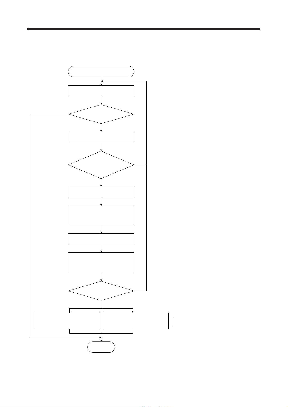
3) Vibration suppression control tuning procedure
The following flow chart is for the vibration suppression control 1. For the vibration suppression
control 2, set "_ _ 1 _" in [Pr. PX03] to execute the vibration suppression control tuning.
No
Vibration suppression control tuning
Operation
Is the target response
reached?
Execute or re-execute vibration
suppression control tuning.
(Set [Pr. PB02] to "_ _ _ 1".)
Decrease the response until vibration
of workpiece end/device is resolved.
End
Yes
No
No
Yes
Increase the response setting.
Has vibration of workpiece
end/device increased?
Has vibration
of workpiece end/device
been resolved?
Using a machine analyzer or
considering load-side vibration
waveform, set the vibration
suppression control manually.
Factor
Estimation cannot be made as load-side vibration
has not been transmitted to the servo motor side.
The response of the model loop gain has
increased to the load-side vibration frequency
(vibration suppression control limit).
Yes
Tuning ends automatically after
positioning operation is performed
the predetermined number of times.
([Pr. PB02] will be "_ _ _ 2" or
"_ _ _ 0".)
Stop operation.
Resume operation.
17. APPLICATION OF FUNCTIONS
17 - 47
4) Vibration suppression control manual mode
POINT
When load-side vibration does not show up in servo motor-side vibration, the
setting of the servo motor-side vibration frequency does not produce an effect.
When the anti-resonance frequency and resonance frequency can be confirmed
using the machine analyzer or external equipment, do not set the same value
but set different values to improve the vibration suppression performance.
The setting range of [Pr. PB19], [Pr. PB20], [Pr. PX04], and [Pr. PX05] varies,
depending on the value in [Pr. PB07]. If a value out of the range is set, the
vibration suppression control will be disabled.
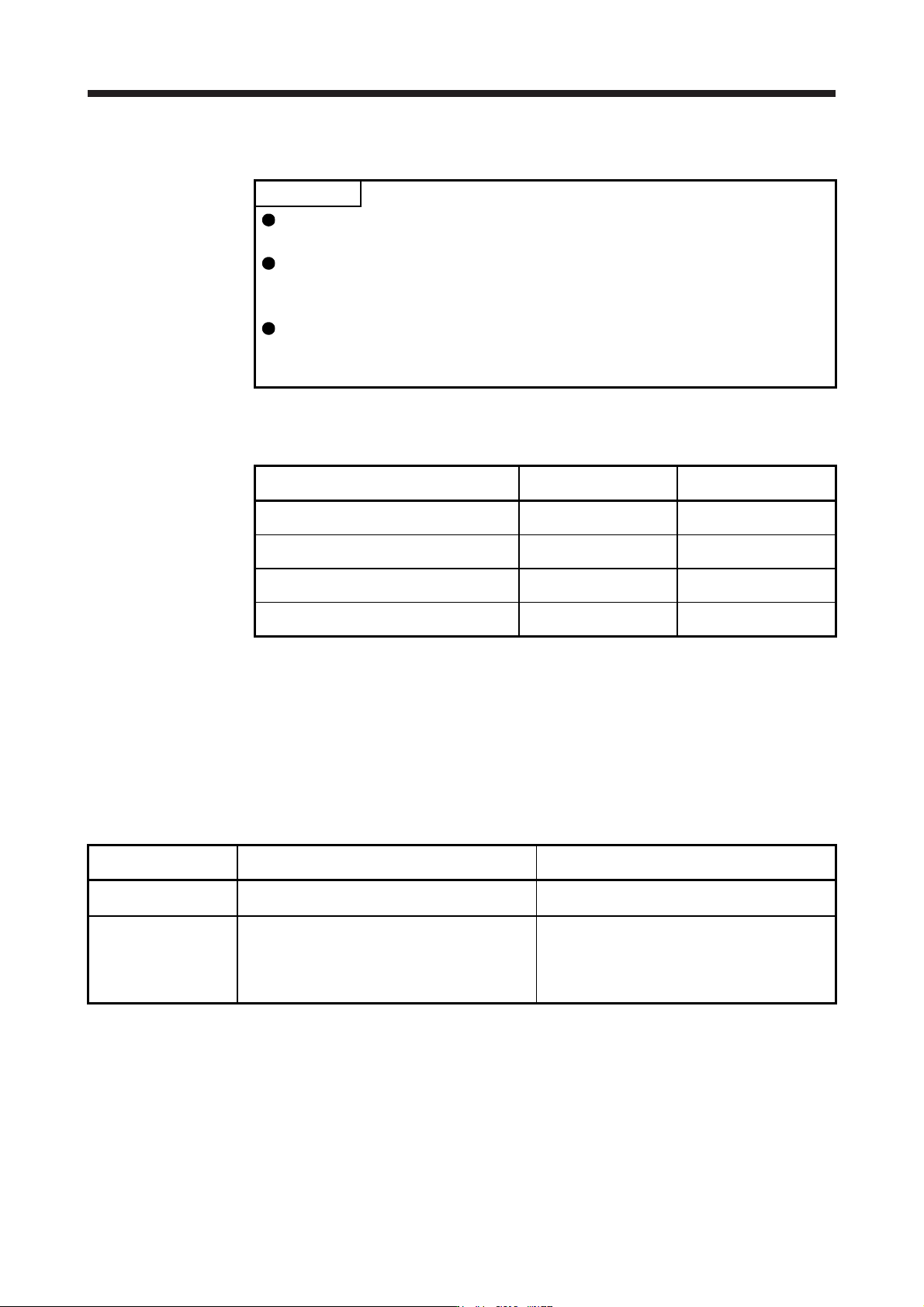
Measure work-side vibration and device shake with the machine analyzer or external measuring
instrument, and set the following parameters to adjust vibration suppression control manually.
Setting item
Vibration suppression
control 1
Vibration suppression
control 2
Vibration suppression control - Vibration
frequency
[Pr. PB19] [Pr. PX04]
Vibration suppression control - Resonance
frequency
[Pr. PB20] [Pr. PX05]
Vibration suppression control - Vibration
frequency damping
[Pr. PB21] [Pr. PX06]
Vibration suppression control - Resonance
frequency damping
[Pr. PB22] [Pr. PX07]
Step 1. Select "Manual setting (_ _ _ 2)" of "Vibration suppression control 1 tuning mode
selection" in [Pr. PB02] or "Manual setting (_ _ 2 _)" of "Vibration suppression control 2
tuning mode selection" in [Pr. PX03].
Step 2. Set "Vibration suppression control - Vibration frequency" and "Vibration suppression
control - Resonance frequency" as follows.
However, the value of [Pr. PB07 Model loop gain], vibration frequency, and resonance frequency
have the following usable range and recommended range.
Vibration suppression
control
Usable range Recommended setting range
Vibration suppression
control 1
[Pr. PB19] > 1/2π × (0.9 × [Pr. PB07])
[Pr. PB20] > 1/2π × (0.9 × [Pr. PB07])
[Pr. PB19] > 1/2π × (1.5 × [Pr. PB07])
[Pr. PB20] > 1/2π × (1.5 × [Pr. PB07])
Vibration suppression
control 2
When [Pr. PB19] < [Pr. PX04],
[Pr. PX04] > (5.0 + 0.1 × [Pr. PB07])
[Pr. PX05] > (5.0 + 0.1 × [Pr. PB07])
1.1 < [Pr. PX04]/[Pr. PB19] < 5.5
[Pr. PB07] < 2π (0.3 × [Pr. PB19] + 1/8 × [Pr. PX04])
When [Pr. PB19] < [Pr. PX04],
[Pr. PX04], [Pr. PX05] > 6.25 Hz
1.1 < [Pr. PX04]/[Pr. PB19] < 4
[Pr. PB07] < 1/3 × (4 × [Pr. PB19] + 2 × [Pr. PX04])
17. APPLICATION OF FUNCTIONS
17 - 48
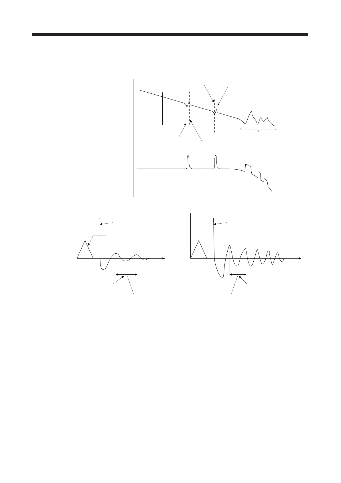
a) When a vibration peak can be confirmed with machine analyzer using MR Configurator2, or
external equipment.
1 Hz
Gain characteristics
Phase
-90 degrees
300 Hz
Vibration suppression control 1 -
Vibration frequency
(anti-resonance frequency)
[Pr. PB19]
Vibration suppression control 1 -
Resonance frequency
[Pr. PB20]
Vibration suppression control 2 -
Vibration frequency
(anti-resonance frequency)
[Pr. PX04]
Vibration suppression control 2 -
Resonance frequency
[Pr. PX05]
Resonance of more than
300 Hz is not the target of control.
b) When vibration can be confirmed using monitor signal or external sensor
t
Motor-side vibration
(droop pulses)
Position command frequency
t
External acceleration pickup signal, etc.
Vibration suppression control -
Vibration frequency
Vibration suppression control -
Resonance frequency
Set the same value.
Vibration cycle [Hz] Vibration cycle [Hz]
Step 3. Fine-adjust "Vibration suppression control - Vibration frequency damping" and "Vibration
suppression control - Resonance frequency damping".
(6) Gain switching function
You can switch gains with the function. You can switch gains during rotation and during stop, and can
use a control command from a controller to switch gains during operation.
(a) Use
The following shows when you use the function.
1) You want to increase the gains during servo-lock but decrease the gains to reduce noise during
rotation.
2) You want to increase the gains during settling to shorten the stop settling time.
3) You want to change the gains using a control command from a controller to ensure stability of the
servo system since the load to motor inertia ratio varies greatly during a stop (e.g. a large load is
mounted on a carrier).