sh030106u.pdf - 第173页
5. PARAMETE RS 5 - 28 No. Sym bol Name and function Initial value [unit] Setting range PB26 *CDP Gain switching f unction Select the gain switc hing condition. Set conditi ons to enable the gain switc hing values set i n…
5. PARAMETERS
5 - 27
No. Symbol Name and function
Initial
value
[unit]
Setting
range
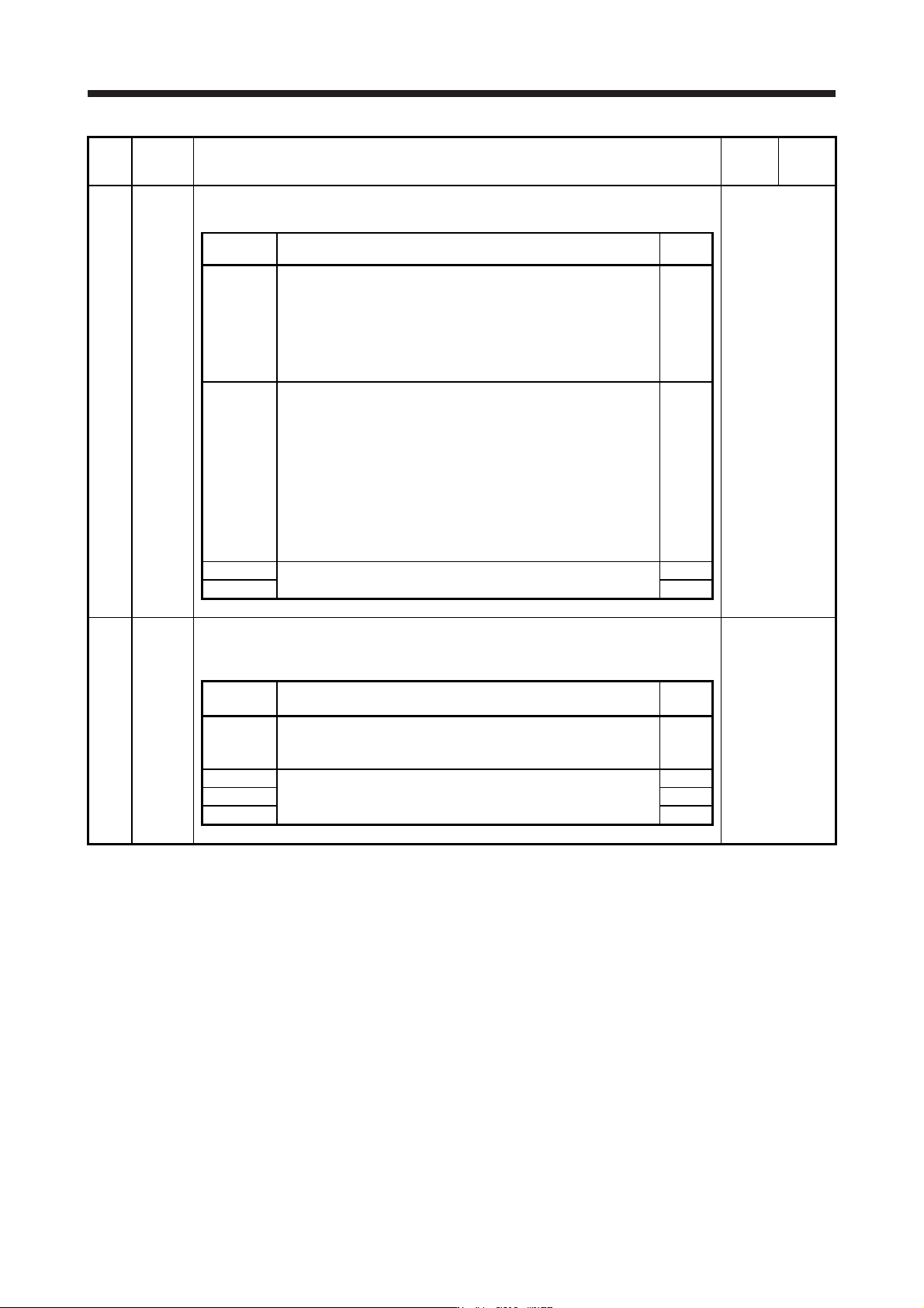
PB24 *MVS Slight vibration suppression control
Select the slight vibration suppression control and PI-PID switching control.
Refer to the
"Name and
function" column.
Setting
digit
Explanation
Initial
value
_ _ _ x Slight vibration suppression control selection
0: Disabled
1: Enabled
To enable the slight vibration suppression control, select "Manual
mode (_ _ _ 3)" of "Gain adjustment mode selection" in [Pr. PA08].
Slight vibration suppression control cannot be used in the speed
control mode.
0h
_ _ x _ PI-PID switching control selection
0: PI control enabled
(The control can be switched to PID control (proportional control)
with the servo system controller command.)
3: Continuous PID control (proportional control) enabled
If the servo motor at a stop is rotated even for a pulse due to any
external factor, it generates torque to compensate for a position
shift. When the servo motor shaft is to be locked mechanically after
positioning completion (stop), enabling PID control and completing
positioning simultaneously will suppress the unnecessary torque
generated to compensate for a position shift.
0h
_ x _ _ For manufacturer setting 0h
x _ _ _ 0h
PB25 *BOP1 Function selection B-1
Select enabled/disabled of model adaptive control.
This parameter is supported with software version B4 or later.
Refer to the
"Name and
function" column.
Setting
digit
Explanation
Initial
value
_ _ _ x Model adaptive control selection
0: Enabled (model adaptive control)
2: Disabled (PID control)
0h
_ _ x _ For manufacturer setting 0h
_ x _ _ 0h
x _ _ _ 0h
5. PARAMETERS
5 - 28
No. Symbol Name and function
Initial
value
[unit]
Setting
range
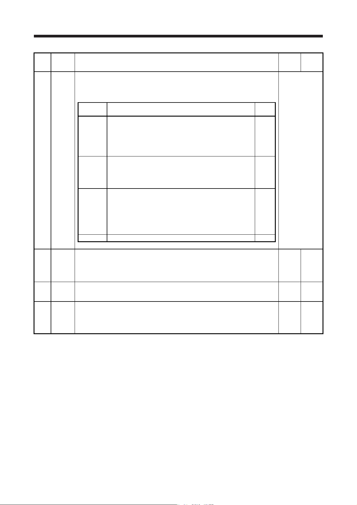
PB26 *CDP Gain switching function
Select the gain switching condition.
Set conditions to enable the gain switching values set in [Pr. PB29] to [Pr. PB36] and [Pr.
PB56] to [Pr. PB60].
Refer to the
"Name and
function" column.
Setting
digit
Explanation
Initial
value
_ _ _ x Gain switching selection
0: Disabled
1: Control command from controller is enabled
2: Command frequency
3: Droop pulses
4: Servo motor speed/linear servo motor speed
0h
_ _ x _ Gain switching condition selection
0: Gain after switching is enabled with gain switching condition or
more
1: Gain after switching is enabled with gain switching condition or
less
0h
_ x _ _ Gain switching time constant disabling condition selection
0: Switching time constant enabled
1: Switching time constant disabled
2: Return time constant disabled
Refer to section 7.2.4 for details.
This parameter is used by servo amplifier with software version B4
or later.
0h
x _ _ _ For manufacturer setting 0h
PB27 CDL Gain switching condition
This is used to set the value of gain switching (command frequency, droop pulses, and servo
motor speed/linear servo motor speed) selected in [Pr. PB26].
The set value unit differs depending on the switching condition item. (Refer to section 7.2.3.)
The unit "r/min" will be "mm/s" for linear servo motors.
10
[kpulse/s]
/[pulse]
/[r/min]
0 to
65535
PB28 CDT Gain switching time constant
This is used to set the time constant until the gains switch in response to the conditions set in
[Pr. PB26] and [Pr. PB27].
1
[ms]
0 to 100
PB29 GD2B Load to motor inertia ratio/load to motor mass ratio after gain switching
This is used to set the load to motor inertia ratio/load to motor mass ratio for when gain
switching is enabled.
This parameter is enabled only when you select "Manual mode (_ _ _ 3)" of "Gain adjustment
mode selection" in [Pr. PA08].
7.00
[Multiplier]
0.00 to
300.00
5. PARAMETERS
5 - 29
No. Symbol Name and function
Initial
value
[unit]
Setting
range
PB30 PG2B
Position loop gain after gain switching
Set the position loop gain when the gain switching is enabled.
When you set a value less than 1.0 rad/s, the value will be the same as [Pr. PB08].
This parameter is enabled only when you select "Manual mode (_ _ _ 3)" of "Gain adjustment
mode selection" in [Pr. PA08].
0.0
[rad/s]
0.0 to
2000.0
PB31 VG2B
Speed loop gain after gain switching
Set the speed loop gain when the gain switching is enabled.
When you set a value less than 20 rad/s, the value will be the same as [Pr. PB09].
This parameter is enabled only when you select "Manual mode (_ _ _ 3)" of "Gain adjustment
mode selection" in [Pr. PA08].
0
[rad/s]
0 to
65535
PB32 VICB
Speed integral compensation after gain switching
Set the speed integral compensation when the gain changing is enabled.
When you set a value less than 0.1 ms, the value will be the same as [Pr. PB10].
This parameter is enabled only when you select "Manual mode (_ _ _ 3)" of "Gain adjustment
mode selection" in [Pr. PA08].
0.0
[ms]
0.0 to
5000.0
PB33 VRF11B
Vibration suppression control 1 - Vibration frequency after gain switching
Set the vibration frequency of the vibration suppression control 1 for when the gain switching
is enabled.
When you set a value less than 0.1 Hz, the value will be the same as [Pr. PB19].
This parameter is enabled only when the following conditions are fulfilled.
"Gain adjustment mode selection" in [Pr. PA08] is "Manual mode (_ _ _ 3)".
"Vibration suppression control 1 tuning mode selection" in [Pr. PB02] is "Manual setting (_ _
_ 2)".
"Gain switching selection" in [Pr. PB26] is "Control command from controller is enabled (_ _
_ 1)".
Switching during driving may cause a shock. Be sure to switch them after the servo motor or
linear servo motor stops.
0.0
[Hz]
0.0 to
300.0
PB34 VRF12B Vibration suppression control 1 - Resonance frequency after gain switching
Set the resonance frequency for vibration suppression control 1 when the gain switching is
enabled.
When you set a value less than 0.1 Hz, the value will be the same as [Pr. PB20].
This parameter will be enabled only when the following conditions are fulfilled.
"Gain adjustment mode selection" in [Pr. PA08] is "Manual mode (_ _ _ 3)".
"Vibration suppression control 1 tuning mode selection" in [Pr. PB02] is "Manual setting (_ _
_ 2)".
"Gain switching selection" in [Pr. PB26] is "Control command from controller is enabled (_ _
_ 1)".
Switching during driving may cause a shock. Be sure to switch them after the servo motor or
linear servo motor stops.
0.0
[Hz]
0.0 to
300.0
PB35 VRF13B Vibration suppression control 1 - Vibration frequency damping after gain switching
Set a damping of the vibration frequency for vibration suppression control 1 when the gain
switching is enabled.
This parameter will be enabled only when the following conditions are fulfilled.
"Gain adjustment mode selection" in [Pr. PA08] is "Manual mode (_ _ _ 3)".
"Vibration suppression control 1 tuning mode selection" in [Pr. PB02] is "Manual setting (_ _
_ 2)".
"Gain switching selection" in [Pr. PB26] is "Control command from controller is enabled (_ _
_ 1)".
Switching during driving may cause a shock. Be sure to switch them after the servo motor or
linear servo motor stops.
0.00 0.00
to
0.30
PB36 VRF14B Vibration suppression control 1 - Resonance frequency damping after gain switching
Set a damping of the resonance frequency for vibration suppression control 1 when the gain
switching is enabled.
This parameter will be enabled only when the following conditions are fulfilled.
"Gain adjustment mode selection" in [Pr. PA08] is "Manual mode (_ _ _ 3)".
"Vibration suppression control 1 tuning mode selection" in [Pr. PB02] is "Manual setting (_ _
_ 2)".
"Gain switching selection" in [Pr. PB26] is "Control command from controller is enabled (_ _
_ 1)".
Switching during driving may cause a shock. Be sure to switch them after the servo motor or
linear servo motor stops.
0.00 0.00
to
0.30