sh030106u.pdf - 第476页
14. USIN G A LINEAR SER VO MOTOR 14 - 9 (3) Settings of th e linear e ncod er direct ion and the line ar ser v o motor dir ection POINT If an incorrect v alue is set for [Pr. PC27], the s ervo mo tor ma y not o perat e p…
14. USING A LINEAR SERVO MOTOR
14 - 8
14.3 Operation and functions
14.3.1 Startup
POINT
When using the linear servo motor, set [Pr. PA01] to "_ _ 4 _".
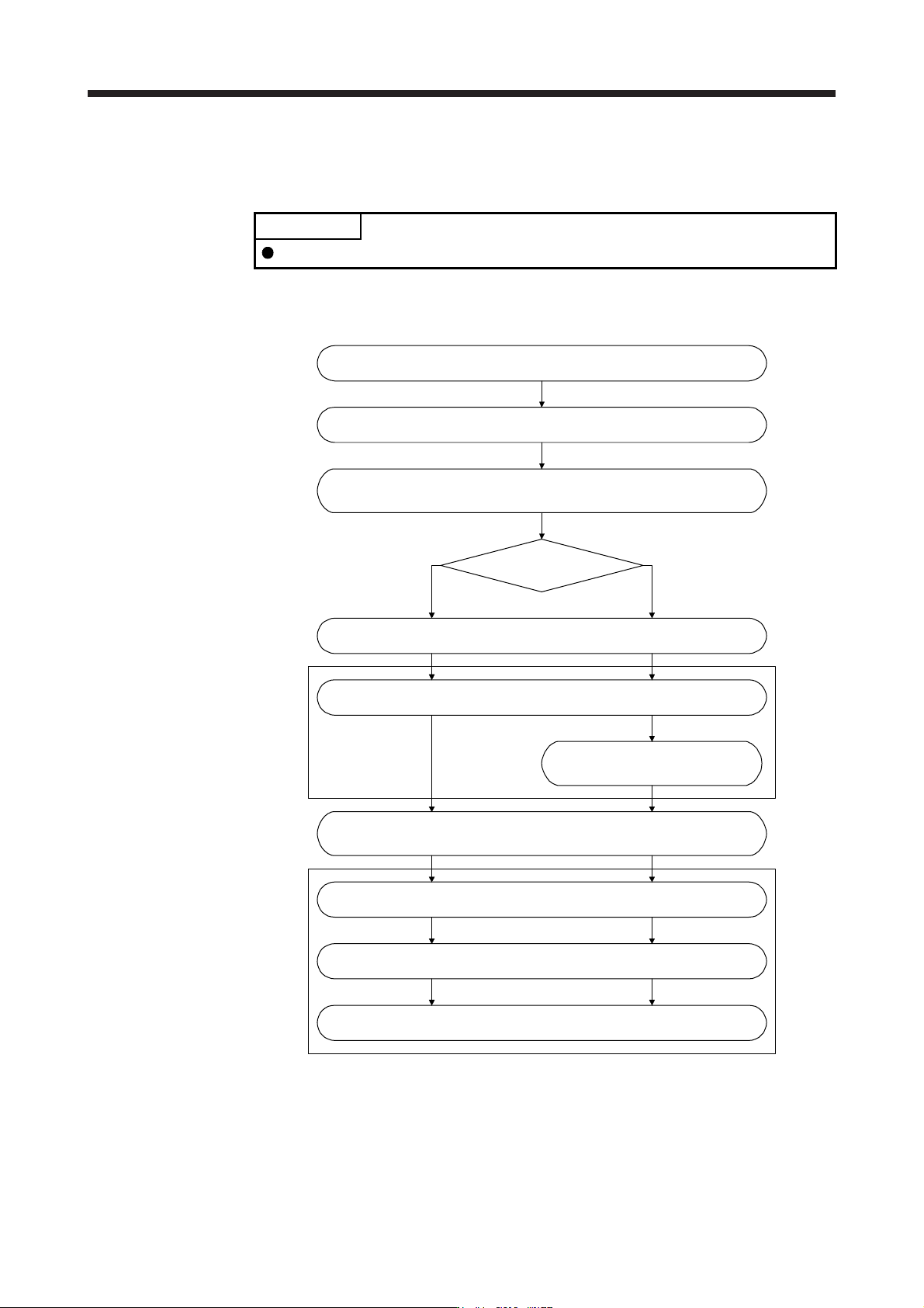
(1) Startup procedure
Start up the linear servo system in the following procedure.
Set the linear servo motor series and linear servo motor type.
(Refer to (2) in this section.)
(Note)
Set the linear encoder direction and the linear servo motor direction.
(Refer to (3) in this section.)
(Note)
Set the linear encoder resolution. (Refer to (4) in this section.)
Change the setting to disable the
magnetic pole detection.
(Refer to (3) of section 14.3.2.)
What is the type of the
linear encoder?
Installation and wiring
(Note)
Perform the magnetic pole detection. (Refer to (3) of section 14.3.2.)
(Note)
Positioning operation check using the test operation mode
(Refer to section 14.3.4.)
Positioning operation check using the controller (Refer to section 14.3.5.)
Home position return operation (Refer to section 14.3.3.)
Positioning operation
Incremental linear encoder Absolute position linear encoder
Note. Use MR Confi
g
urator2.
(2) Set the linear servo motor series and linear servo motor type.
To use the linear servo motor, set the linear servo motor series and linear servo motor type with [Pr.
PA17 Servo motor series setting] and [Pr. PA18 Servo motor type setting]. (Refer to section 5.2.1.)
14. USING A LINEAR SERVO MOTOR
14 - 9
(3) Settings of the linear encoder direction and the linear servo motor direction
POINT
If an incorrect value is set for [Pr. PC27], the servo motor may not operate
properly, or [AL. 50] or [AL. 51] may occur at the positioning operation or the
magnetic pole detection.
Set the first digit of [Pr. PC27] (Encoder pulse count polarity selection) so that the positive direction of
the linear servo motor matches with the increasing direction of the linear encoder feedback.
[Pr. PC27]
Encoder pulse count polarity selection
0: Linear servo motor positive direction and linear encoder increasing direction
1: Linear servo motor positive direction and linear encoder decreasing direction
(a) Parameter setting method
1) Confirm the positive direction of the linear servo motor. [Pr. PA14] determines the relation of the
travel direction of the linear servo motor under commands as shown below.
[Pr. PA14] setting
Travel direction of linear servo motor
Address increasing
command
Address decreasing
command
0 Positive direction Negative direction
1 Negative direction Positive direction
The positive/negative directions of the linear servo motor are as follows.
Secondary
side
Primary side
Positive
direction
Ne
g
ative
direction
LM-H3 and LM-F series
Negative direction
Positive
direction
Secondary side
Primary
side
LM-U2 series
Negative
direction
Positive
direction
Table
Primary
side
Secondary
side
LM-K2 series
2) Confirm the increasing direction of the linear encoder.
3) If the positive direction of the linear servo motor matches with the increasing direction of the linear
encoder, set [Pr. PC27] to "_ _ _ 0". If the positive direction of the linear servo motor does not
match with the increasing direction of the linear encoder, set [Pr. PC27] to "_ _ _ 1".
14. USING A LINEAR SERVO MOTOR
14 - 10
(b) Confirmation method
Confirm the positive direction of the linear servo motor and the increasing direction of the linear
encoder in the following procedure.
1) In servo-off status, move the linear servo motor in the positive direction manually.
2) Confirm the motor speed (in the positive and negative directions) at that time with MR
Configurator2.
3) When [Pr. PC27] is set to "_ _ _ 0" and the positive direction of the linear servo motor matches
with the increasing direction of the linear encoder, if the linear servo motor operates in the
positive direction, the motor speed will be a positive value. If the positive direction of the linear
servo motor does not match with the increasing direction of the linear encoder, the motor speed
will be a negative value. When [Pr. PC27] is set to "_ _ _ 1" and the positive direction of the linear
servo motor matches with the increasing direction of the linear encoder, if the linear servo motor
operates in the positive direction, the motor speed will be a negative value.
(4) Linear encoder resolution setting
POINT
To enable the parameter value, cycle the power after setting.
If an incorrect value is set for [Pr. PL02] or [Pr. PL03], the linear servo motor
may not operate properly, or [AL. 27] or [AL. 42] may occur at the positioning
operation or the magnetic pole detection.
Set the ratio of the electronic gear to the linear encoder resolution with [Pr. PL02 Linear encoder
resolution - Numerator] and [Pr. PL03 Linear encoder resolution - Denominator].
(a) Parameter setting
Set the values that apply to the following equation.
[Pr. PL02 Linear encoder resolution - Numerator]
[Pr. PL03 Linear encoder resolution - Denominator]
= Linear encoder resolution [µm]
(b) Parameter setting example
When the linear encoder resolution is 0.5 µm
[Pr. PL02]
[Pr. PL03]
= Linear encoder resolution = 0.5 µm =
2
1
The following shows the simplified chart for the setting values of [Pr. PL02] and [Pr. PL03].
Linear encoder resolution [µm]
0.01 0.02 0.05 0.1 0.2 0.5 1.0 2.0
Setting
value
[Pr. PL02] 1 1 1 1 1 1 1 2
[Pr. PL03] 100 50 20 10 5 2 1 1