sh030106u.pdf - 第576页
17. APPLICATIO N OF FUNCTIONS 17 - 25 No. Sym bol Name and function Initial value [unit] Setting range PX38 LMFLT Lost motion filter sett ing Set the time constant o f the lo st motion compensation filter in increments o…

17. APPLICATION OF FUNCTIONS
17 - 24
No. Symbol Name and function
Initial
value
[unit]
Setting
range
PX28 CVAT SEMI-F47 function - Instantaneous power failure detection time
Set the time until the occurrence of [AL. 10.1 Voltage drop in the control circuit power].
This parameter setting range differs depending on the software version of the servo amplifier
as follows.
Software version C0 or later: Setting range 30 ms to 200 ms
Software version C1 or earlier: Setting range 30 ms to 500 ms
To comply with SEMI-F47 standard, it is unnecessary to change the initial value (200 ms).
When the instantaneous power failure time exceeds 200 ms, and if the instantaneous power
failure voltage is less than 70 % of the rated input voltage, the power may be turned off
normally even if a value larger than 200 ms is set in the parameter.
To disable the parameter, set "Disabled (_ 0 _ _)" of "SEMI-F47 function selection" in [Pr.
PX25].
200
[ms]
30
to
500
PX29 DRAT Drive recorder arbitrary alarm trigger setting
Refer to the
"Name and
function" column.
Setting
digit
Explanation
Initial
value
_ _ x x Alarm detail No. setting
Set the digits when you execute the trigger with arbitrary alarm
detail No. for the drive recorder function.
When these digits are "0 0", only the arbitrary alarm No. setting will
be enabled.
00h
x x _ _ Alarm No. setting
Set the digits when you execute the trigger with arbitrary alarm No.
for the drive recorder function.
When "0 0" are set, arbitrary alarm trigger of the drive recorder will
be disabled.
00h
Setting example:
To activate the drive recorder when [AL. 50 Overload 1] occurs, set "5 0 0 0".
To activate the drive recorder when [AL. 50.3 Thermal overload error 4 during operation]
occurs, set "5 0 0 3".
PX30 DRT Drive recorder switching time setting
Set the drive recorder switching time.
When a USB communication is cut during using a graph function, the function will be changed
to the drive recorder function after the setting time of this parameter.
When a value from "1" to "32767" is set, it will switch after the setting value.
However, when "0" is set, it will switch after 600 s.
When "-1" is set, the drive recorder function is disabled.
0
[s]
-1
to
32767
PX31 XOP4 Function selection X-4
Refer to the
"Name and
function" column.
Setting digit Explanation
Initial
value
_ _ _ x Robust filter selection
0: Disabled
1: Enabled
When you select "Enabled" of this digit, the machine resonance
suppression filter 5 set in [Pr. PX22] is not available.
0h
_ _ x _ For manufacturer setting 0h
_ x _ _ 0h
x _ _ _ 0h
PX36 LMCP Lost motion compensation positive-side compensation value selection
Set the lost motion compensation for when reverse rotation (CW) switches to forward rotation
(CCW) in increments of 0.01% assuming the rated torque as 100%.
This parameter is supported with software version B4 or later.
0
[0.01%]
0
to
30000
PX37 LMCN Lost motion compensation negative-side compensation value selection
Set the lost motion compensation for when forward rotation (CCW) switches to reverse
rotation (CW) in increments of 0.01% assuming the rated torque as 100%.
This parameter is supported with software version B4 or later.
0
[0.01%]
0
to
30000
17. APPLICATION OF FUNCTIONS
17 - 25
No. Symbol Name and function
Initial
value
[unit]
Setting
range
PX38 LMFLT Lost motion filter setting
Set the time constant of the lost motion compensation filter in increments of 0.1 ms.
If the time constant is "0", the torque is compensated with the value set in [Pr. PX36] and [Pr.
PX37]. If the time constant is other than "0", the torque is compensated with the high-pass
filter output value of the set time constant, and the lost motion compensation will continue.
This parameter is supported with software version B4 or later.
0
[0.1 ms]
0
to
30000
PX39 TOF Torque offset
Set this when canceling unbalanced torque of vertical axis. Set this assuming the rated torque
of the servo motor as 100%.
The torque offset does not need to be set for a machine not generating unbalanced torque.
The torque offset cannot be used for linear servo motors and direct drive motors. Set 0.00%.
The torque offset set with this parameter will be enabled in the position control mode, speed
control mode, and torque control mode. Input commands assuming torque offset for the
torque control mode.
This parameter is supported with software version B4 or later.
0
[0.01%]
-10000
to
10000
PX40 *LMOP Lost motion compensation function selection
Select the lost motion compensation function.
This parameter is supported with software version B4 or later.
Refer to the
"Name and
function" column.
Setting
value
Explanation
Initial
value
_ _ _ x Lost motion compensation selection
0: Disabled
1: Enabled
0h
_ _ x _ Unit setting of lost motion compensation non-sensitive band
0: 1 pulse unit
1: 1 kpulse unit
0h
_ x _ _ For manufacturer setting 0h
x _ _ _ 0h
PX41 LMCD Lost motion compensation timing
Set the lost motion compensation timing in increments of 0.1 ms.
You can delay the timing to perform the lost motion compensation for the set time.
This parameter is supported with software version B4 or later.
0
[0.1 ms]
0
to
30000
PX42 LMCT Lost motion compensation non-sensitive band
Set the lost motion compensation non-sensitive band. When the fluctuation of the droop pulse
is the setting value or less, the speed will be 0. Setting can be changed in [Pr. PX40]. Set the
parameter per encoder unit.
This parameter is supported with software version B4 or later.
0
[pulse]/
[kpulse]
0
to
65535
PX43 **STOD STO diagnosis error detection time
Set the time from when an error occurs in the STO input signal or STO circuit until the
detection of [AL. 68.1 Mismatched STO signal error].
When 0 s is set, the detection of [AL. 68.1 Mismatched STO signal error] is not performed.
The following shows safety levels at the time of parameter setting.
0
[s]
0
to
60
Setting
value
STO input diagnosis by
TOFB output
Safety level
0
Execute EN ISO 13849-1:2015 Category 3 PL d,
IEC 61508 SIL 2,
EN IEC 62061 maximum SIL 2
Not execute
1 to 60
Execute
EN ISO 13849-1:2015 Category 3 PL e,
IEC 61508 SIL 3,
EN IEC 62061 maximum SIL 3
Not execute
EN ISO 13849-1:2015 Category 3 PL d,
IEC 61508 SIL 2,
EN IEC 62061 maximum SIL 2
When the short-circuit connector is connected to the CN8 connector, set "0" in the parameter.
This parameter is available with servo amplifiers with software version C1 or later.
17. APPLICATION OF FUNCTIONS
17 - 26
(4) One-touch tuning
POINT
After the one-touch tuning is completed, "Gain adjustment mode selection" in
[Pr. PA08] will be set to "2 gain adjustment mode 2 (_ _ _ 4)". To estimate [Pr.
PB06 Load to motor inertia ratio/load to motor mass ratio] again, set "Gain
adjustment mode selection" in [Pr. PA08] to "Auto tuning mode 1 (_ _ _ 1)".
When executing the one-touch tuning, check the [Pr. PX13 One-touch tuning
function selection] is "_ _ _ 1" (initial value).
At start of the one-touch tuning, only when "Auto tuning mode 1 (_ _ _ 1)" or "2
gain adjustment mode 1 (interpolation mode) (_ _ _ 0)" of "Gain adjustment
mode selection" is selected in [Pr. PA08], [Pr. PB06 Load to motor inertia
ratio/load to motor mass ratio] will be estimated.
Execute the one-touch tuning while the servo system controller and the servo
amplifier are connected.
When executing the one-touch tuning in the test operation mode (SW2-1 is on),
write the tuning result to servo parameters of the servo system controller, and
then connect the servo system controller and the servo amplifier.
The amplifier command method can be used with the servo amplifier with
software version C1 or later and MR Configurator2 with software version 1.45X
or later.
When the one-touch tuning is executed, MR Configurator2 is required.
The one-touch tuning includes two methods: the user command method and the amplifier command
method.
1) User command method
The user command method performs one-touch tuning by inputting commands from outside the
servo amplifier.
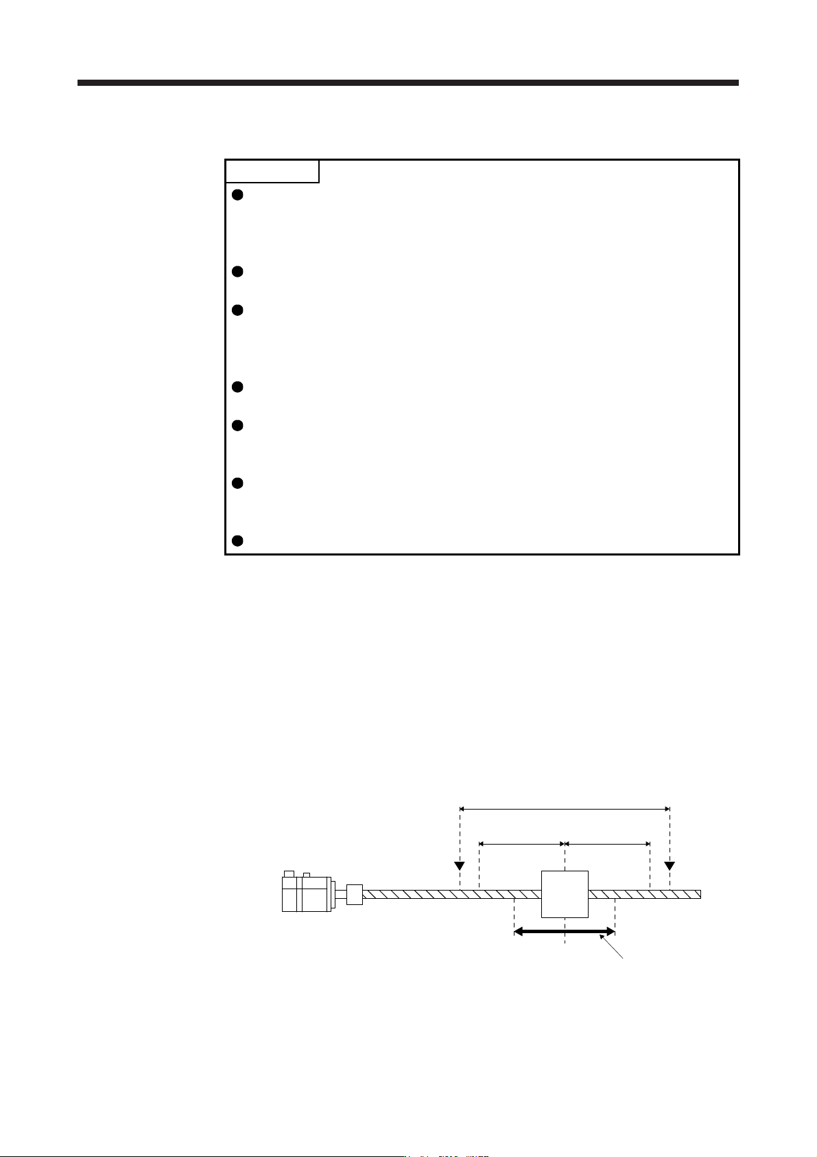
2) Amplifier command method
In the amplifier command method, when you simply input a travel distance (permissible travel
distance) that collision against the equipment does not occur during servo motor driving, a
command for the optimum tuning will be generated inside the servo amplifier to perform one-
touch tuning.
Servo motor
Moving
part
Movable range
Tuning start position
Movable range at tuning
Permissible
travel distance
Limit switch
Permissible
travel distance
Limit switch