sh030106u.pdf - 第246页
7. SPEC IAL ADJUSTMEN T FUNCT IONS 7 - 17 7.2.3 Par ameter When usi ng the gain switc hing function, always select " Manu al m o de (_ _ _ 3)" of "Gain adjustme nt mode selection" in [Pr. PA08 Auto tu…
7. SPECIAL ADJUSTMENT FUNCTIONS
7 - 16
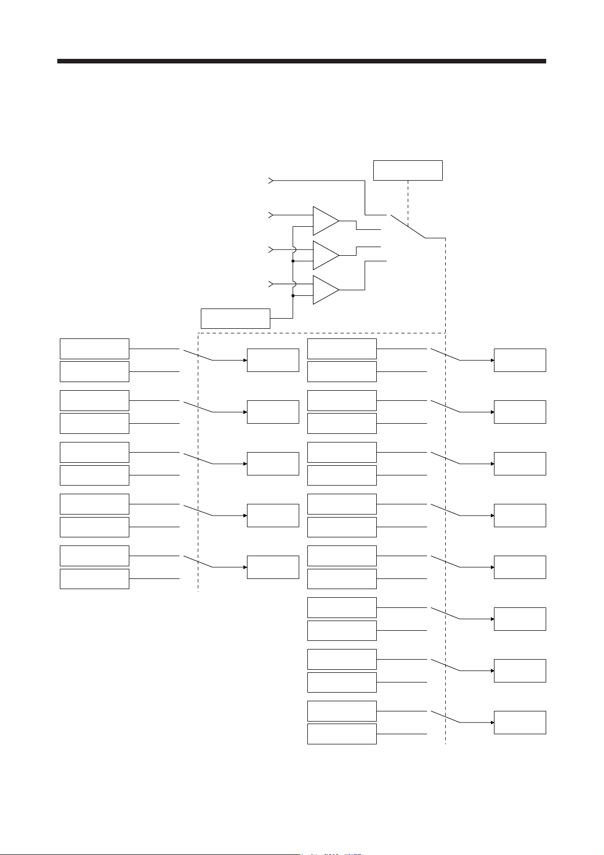
7.2.2 Function block diagram
The control gains, load to motor inertia ratio, and vibration suppression control settings are changed
according to the conditions selected by [Pr. PB26 Gain switching function] and [Pr. PB27 Gain switching
condition].
Command pulse
frequency
+
-
Droop pulses
Model speed
Control command
from controller
Comparator
Changing
CDP
[Pr. PB26]
+
-
+
-
GD2
[Pr. PB06]
GD2B
[Pr. PB29]
Enabled
GD2 value
PG1
[Pr. PB07]
PG1B
[Pr. PB60]
Enabled
PG1 value
PG2
[Pr. PB08]
PG2B
[Pr. PB30]
Enabled
PG2 value
VG2
[Pr. PB09]
VG2B
[Pr. PB31]
Enabled
VG2 value
VIC
[Pr. PB10]
VICB
[Pr. PB32]
Enabled
VIC value
VRF11
[Pr. PB19]
VRF11B
[Pr. PB33]
Enabled
VRF11 value
VRF12
[Pr. PB20]
VRF12B
[Pr. PB34]
Enabled
VRF12 value
CDL
[Pr. PB27]
VRF13
[Pr. PB21]
VRF13B
[Pr. PB35]
Enabled
VRF13 value
VRF14
[Pr. PB22]
VRF14B
[Pr. PB36]
Enabled
VRF14 value
VRF21
[Pr. PB52]
VRF21B
[Pr. PB56]
Enabled
VRF21 value
VRF22
[Pr. PB53]
VRF22B
[Pr. PB57]
Enabled
VRF22 value
VRF23
[Pr. PB54]
VRF23B
[Pr. PB58]
Enabled
VRF23 value
VRF24
[Pr. PB55]
VRF24B
[Pr. PB59]
Enabled
VRF24 value
7. SPECIAL ADJUSTMENT FUNCTIONS
7 - 17
7.2.3 Parameter
When using the gain switching function, always select "Manual mode (_ _ _ 3)" of "Gain adjustment mode
selection" in [Pr. PA08 Auto tuning mode]. The gain switching function cannot be used in the auto tuning
mode.
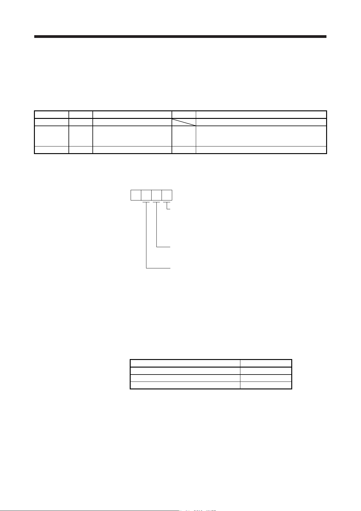
(1) Parameter for setting gain switching condition
Parameter Symbol Name Unit Description
PB26 CDP Gain switching function Select a switching condition.
PB27 CDL Gain switching condition [kpulse/s]
/[pulse]
/[r/min]
Set a switching condition values.
PB28 CDT Gain switching time constant [ms] Set the filter time constant for a gain change at switching.
(a) [Pr. PB26 Gain switching function]
Used to set the gain switching condition. Select the switching condition in the first to third digits.
Gain switching selection
0: Disabled
1: Control command from controller is enabled
2: Command frequency
3: Droop pulses
4: Servo motor speed/linear servo motor speed
0
Gain switching condition
0: Gain after switching is enabled with gain switching condition or mor
e
1: Gain after switching is enabled with gain switching condition or less
[Pr. PB26]
Gain switching time constant disabling condition selection (Note)
0: Switching time constant enabled
1: Switching time constant disabled
2: Return time constant disabled
Note. This di
g
it is available with servo amplifier with software version B4 or later.
(b) [Pr. PB27 Gain switching condition]
Set a level to switch gains with [Pr. PB27] after you select "Command frequency", "Droop pulses", or
"Servo motor speed/linear servo motor speed" with the gain switching selection in [Pr. PB26 Gain
switching function].
The setting unit is as follows.
Gain switching condition Unit
Command frequency [kpulse/s]
Droop pulses [pulse]
Servo motor speed/linear servo motor speed [r/min]/[mm/s]
(c) [Pr. PB28 Gain switching time constant]
You can set the primary delay filter to each gain at gain switching. This parameter is used to
suppress shock given to the machine if the gain difference is large at gain switching, for example.
7. SPECIAL ADJUSTMENT FUNCTIONS
7 - 18
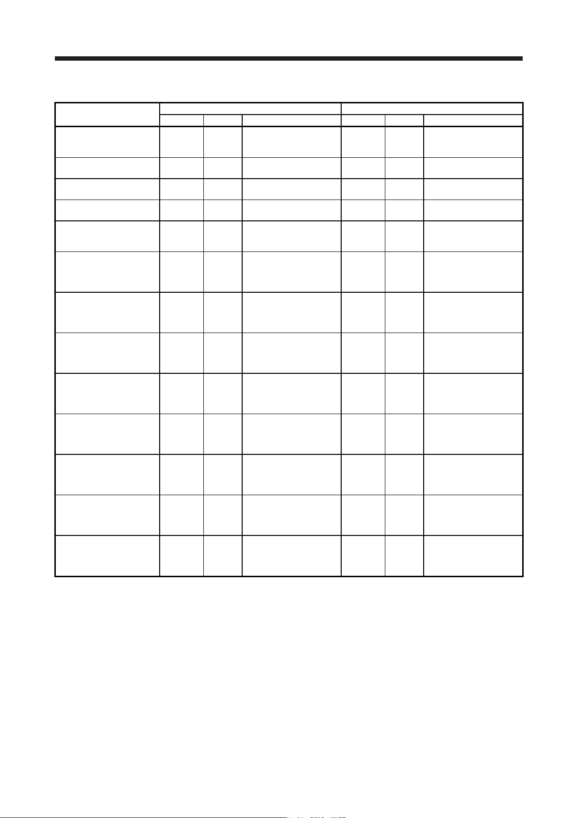
(2) Switchable gain parameter
Loop gain
Before switching After switching
Parameter Symbol Name Parameter Symbol Name
Load to motor inertia
ratio/load to motor mass
ratio
PB06 GD2
Load to motor inertia
ratio/load to motor mass
ratio
PB29 GD2B
Load to motor inertia
ratio/load to motor mass
ratio after gain switching
Model loop gain PB07 PG1 Model loop gain PB60 PG1B
Model loop gain after gain
switching
Position loop gain PB08 PG2 Position loop gain PB30 PG2B
Position loop gain after
gain switching
Speed loop gain PB09 VG2 Speed loop gain PB31 VG2B
Speed loop gain after gain
switching
Speed integral
compensation
PB10 VIC
Speed integral
compensation
PB32 VICB
Speed integral
compensation after gain
switching
Vibration suppression
control 1 - Vibration
frequency
PB19 VRF11
Vibration suppression
control 1 - Vibration
frequency
PB33 VRF11B
Vibration suppression
control 1 - Vibration
frequency after gain
switching
Vibration suppression
control 1 - Resonance
frequency
PB20 VRF12
Vibration suppression
control 1 - Resonance
frequency
PB34 VRF12B
Vibration suppression
control 1 - Resonance
frequency after gain
switching
Vibration suppression
control 1 - Vibration
frequency damping
PB21 VRF13
Vibration suppression
control 1 - Vibration
frequency damping
PB35 VRF13B
Vibration suppression
control 1 - Vibration
frequency damping after
gain switching
Vibration suppression
control 1 - Resonance
frequency damping
PB22 VRF14
Vibration suppression
control 1 - Resonance
frequency damping
PB36 VRF14B
Vibration suppression
control 1 - Resonance
frequency damping after
gain switching
Vibration suppression
control 2 - Vibration
frequency
PB52 VRF21
Vibration suppression
control 2 - Vibration
frequency
PB56 VRF21B
Vibration suppression
control 2 - Vibration
frequency after gain
switching
Vibration suppression
control 2 - Resonance
frequency
PB53 VRF22
Vibration suppression
control 2 - Resonance
frequency
PB57 VRF22B
Vibration suppression
control 2 - Resonance
frequency after gain
switching
Vibration suppression
control 2 - Vibration
frequency damping
PB54 VRF23
Vibration suppression
control 2 - Vibration
frequency damping
PB58 VRF23B
Vibration suppression
control 2 - Vibration
frequency damping after
gain switching
Vibration suppression
control 2 - Resonance
frequency damping
PB55 VRF24
Vibration suppression
control 2 - Resonance
frequency damping
PB59 VRF24B
Vibration suppression
control 2 - Resonance
frequency damping after
gain switching
(a) [Pr. PB06] to [Pr. PB10]
These parameters are the same as in ordinary manual adjustment. Gain switching allows the values
of load to motor inertia ratio/load to motor mass ratio, model loop gain, position loop gain, speed loop
gain, and speed integral compensation to be switched.
(b) [Pr. PB19] to [Pr. PB22]/[Pr. PB52] to [Pr. PB55]
These parameters are the same as in ordinary manual adjustment. Executing gain switching while
the servo motor stops, You can change vibration frequency, resonance frequency, vibration
frequency damping, and resonance frequency damping.