sh030106u.pdf - 第252页
7. SPEC IAL ADJUSTMEN T FUNCT IONS 7 - 23 (b) Return t ime cons tant d isabl ed was se lected. The gain sw itching t ime co nstant is enabl ed. The t ime c onstant is disabl ed at g ain retur n. The foll owing exa mple s…
7. SPECIAL ADJUSTMENT FUNCTIONS
7 - 22
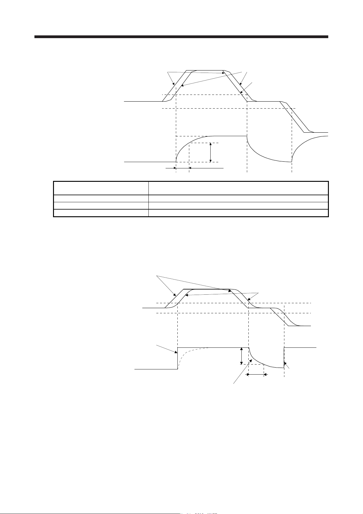
(b) Switching timing chart
After-switching gain
63.4%
CDT = 100 ms
Before-switching gain
Gain switching
Droop pulses
[pulse]
+CDL
-CDL
0
Command pulses
Droop pulses
Command pulses
Load to motor inertia ratio/load to motor
mass ratio
4.00 → 10.00 → 4.00 → 10.00
Position loop gain 120 → 84 → 120 → 84
Speed loop gain 3000 → 4000 → 3000 → 4000
Speed integral compensation 20 → 50 → 20 → 50
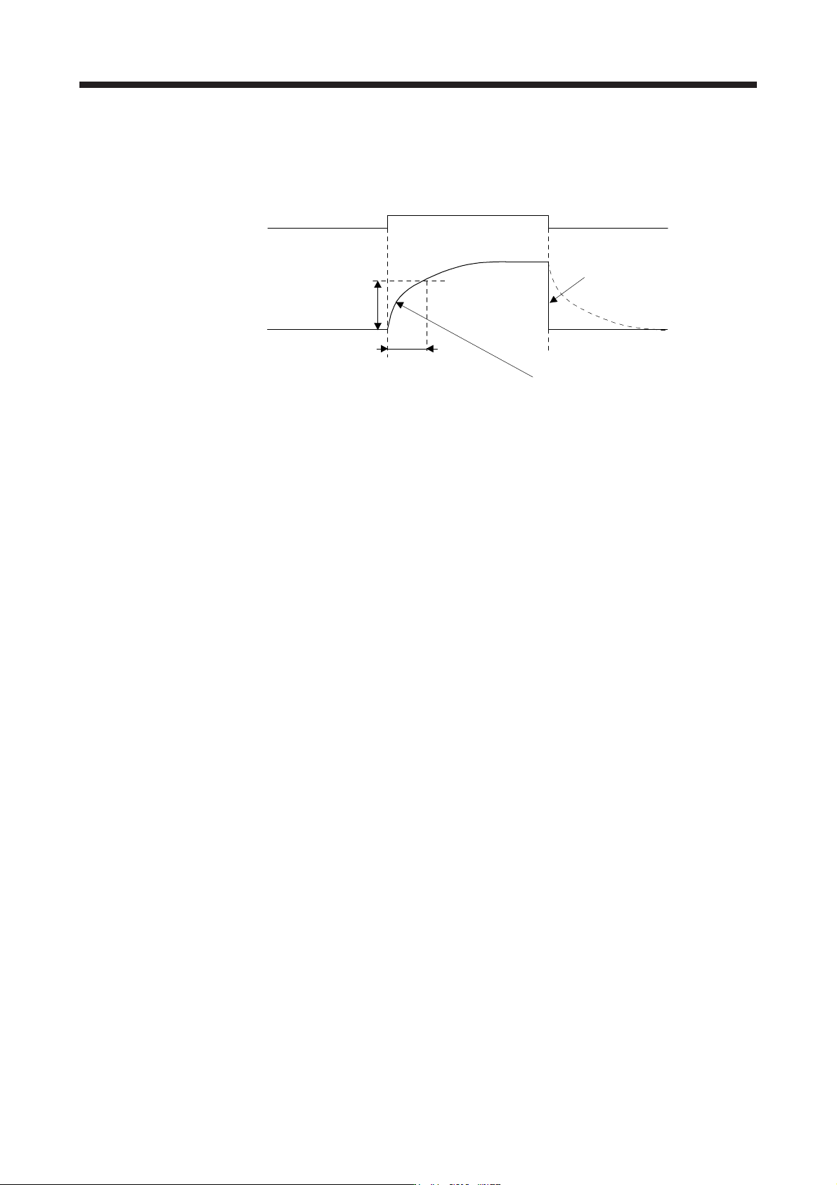
(3) When the gain switching time constant is disabled
(a) Switching time constant disabled was selected.
The gain switching time constant is disabled. The time constant is enabled at gain return.
The following example shows for [Pr. PB26 (CDP)] = 0103, [Pr. PB27 (CDL)] = 100 [pulse], and [Pr.
PB28 (CDT)] = 100 [ms].
Command pulses
Droop pulses
+100 pulses
-100 pulses
0Droop pulses [pulse]
Switching time constant
disabled
Switching at 0 ms
After-switching gain
Before-switching gain
Switching at [Pr. PB28 (CDT)] = 100 [ms] only when gain switching off (when returning)
CDT = 100 ms
63.4%
Switching at 0 ms
After-switching gain
Gain switching
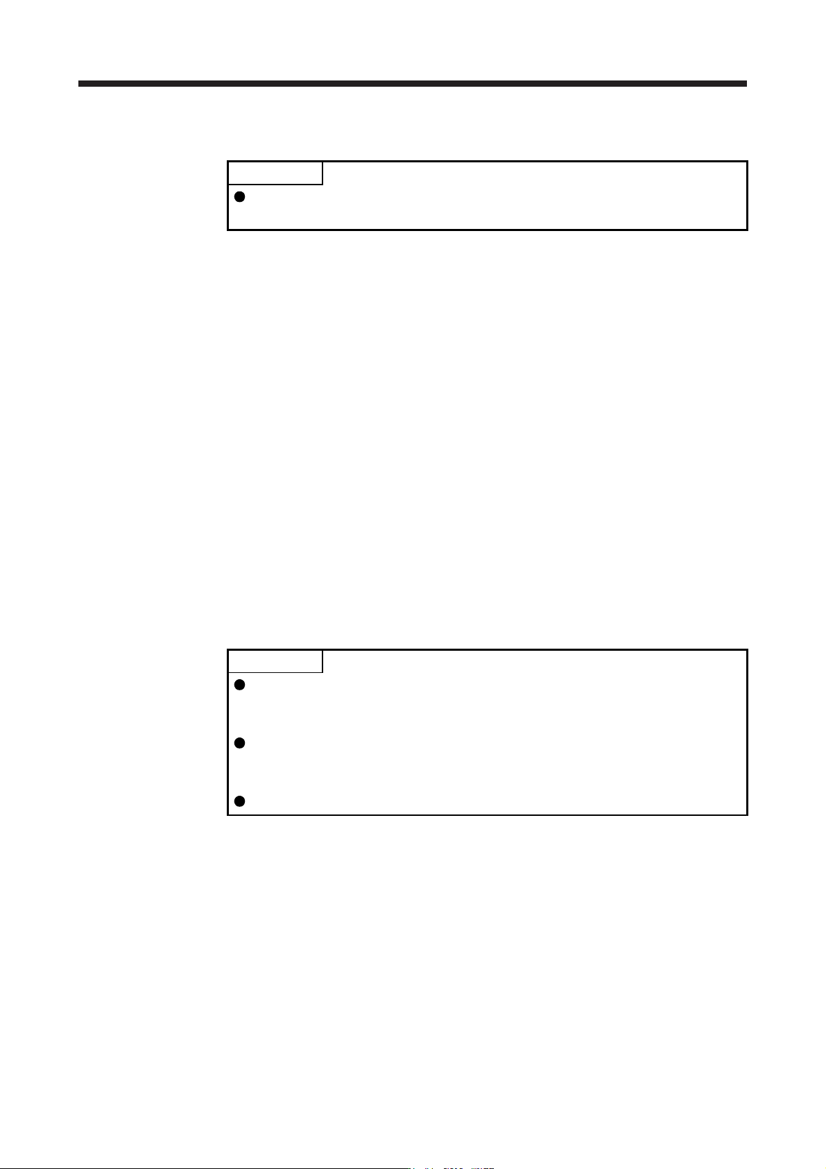
7. SPECIAL ADJUSTMENT FUNCTIONS
7 - 23
(b) Return time constant disabled was selected.
The gain switching time constant is enabled. The time constant is disabled at gain return.
The following example shows for [Pr. PB26 (CDP)] = 0201, [Pr. PB27 (CDL)] = 0, and [Pr. PB28
(CDT)] = 100 [ms].
ONCDP (Gain switching)
After-switching gain
Before-switching gain
Switching at [Pr. PB28 (CDT)] = 100 [ms] only when gain switching on (when switching)
CDT = 100 ms
Return time constant disabled
Switching at 0 ms
OFF OFF
63.4%
Gain switching
7. SPECIAL ADJUSTMENT FUNCTIONS
7 - 24
7.3 Tough drive function
POINT
Set enable/disable of the tough drive function with [Pr. PA20 Tough drive
setting]. (Refer to section 5.2.1.)
This function makes the equipment continue operating even under the condition that an alarm occurs.
The tough drive functions are the vibration tough drive and the instantaneous power failure tough drive.
7.3.1 Vibration tough drive function
This function prevents vibration by resetting a filter instantaneously when machine resonance occurs due to
varied vibration frequency caused by machine aging.
To reset the machine resonance suppression filters with the function, [Pr. PB13 Machine resonance
suppression filter 1] and [Pr. PB15 Machine resonance suppression filter 2] should be set in advance.
Set [Pr. PB13] and [Pr. PB15] as follows.
(1) One-touch tuning execution (section 6.1)
(2) Manual setting (section 4.2.2)
The vibration tough drive function operates when a detected machine resonance frequency is within ±30%
for a value set in [Pr. PB13 Machine resonance suppression filter 1] or [Pr. PB15 Machine resonance
suppression filter 2].
To set a detection level of the function, set sensitivity in [Pr. PF23 Vibration tough drive - Oscillation detection
level].
POINT
Resetting [Pr. PB13] and [Pr. PB15] by the vibration tough drive function is
performed constantly. However, the number of write times to the EEPROM is
limited to once per hour.
The vibration tough drive function does not reset [Pr. PB46 Machine resonance
suppression filter 3], [Pr. PB48 Machine resonance suppression filter 4], and [Pr.
PB50 Machine resonance suppression filter 5].
The vibration tough drive function does not detect a vibration of 100 Hz or less.