sh030106u.pdf - 第101页
3. SIG NALS A ND WIRI NG 3 - 24 3.4 Conn ectors and pin ass ignment POINT The pin ass ignment of the connectors is as v iewed fr om the c abl e con nector wiring sec tion. For the STO I/O s ignal c onnecto r (CN8), re fe…
3. SIGNALS AND WIRING
3 - 23
You can also use a ferrule to connect with the connectors. When using a ferrule, select a ferrule and
crimping tool listed in the table below.
Servo amplifier Wire size
Ferrule model (Phoenix Contact)
Crimping tool
(Phoenix Contact)
For one For two
MR-J4-10B(-RJ) to
MR-J4-100B(-RJ)
AWG 16 AI1.5-10BK AI-TWIN2×1.5-10BK
CRIMPFOX-ZA3
AWG 14 AI2.5-10BU
MR-J4-200B(-RJ) to
MR-J4-350B(-RJ)
AWG 16 AI1.5-10BK AI-TWIN2×1.5-10BK
AWG 14 AI2.5-10BU AI-TWIN2×2.5-10BU
AWG 12 AI4-10GY
MR-J4-60B4(-RJ) to
MR-J4-350B4(-RJ)
AWG 16 AI1.5-10BK AI-TWIN2×1.5-10BK
AWG 14 AI2.5-10BU
MR-J4-10B1(-RJ) to
MR-J4-40B1(-RJ)
AWG 16 AI1.5-10BK AI-TWIN2×1.5-10BK
AWG 14 AI2.5-10BU
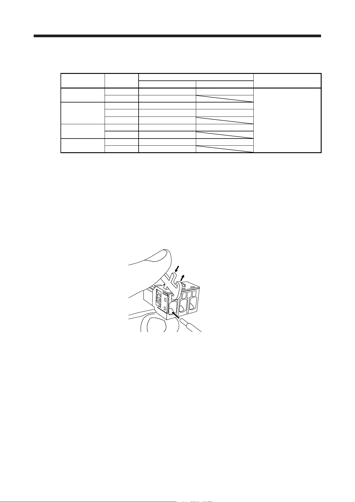
(b) Inserting wire
Insert only one wire or ferrule to each wire insertion hole.
Insert the open tool as follows and push it down to open the spring. While the open tool is pushed
down, insert the stripped wire into the wire insertion hole. Check the wire insertion depth, and make
sure that the cable insulator will not be caught by the spring and that the conductive part of the
stripped wire will not be exposed.
Release the open tool to fix the wire. Pull the wire lightly to confirm that the wire is surely connected.
In addition, make sure that no conductor wire sticks out of the connector.
The following shows a connection example of the CNP3 connector for MR-J4-200B(-RJ) and MR-J4-
350B(-RJ).
1) Push down the open tool.
3) Release the open tool to fix the wire.
2) Insert the wire.
3. SIGNALS AND WIRING
3 - 24
3.4 Connectors and pin assignment
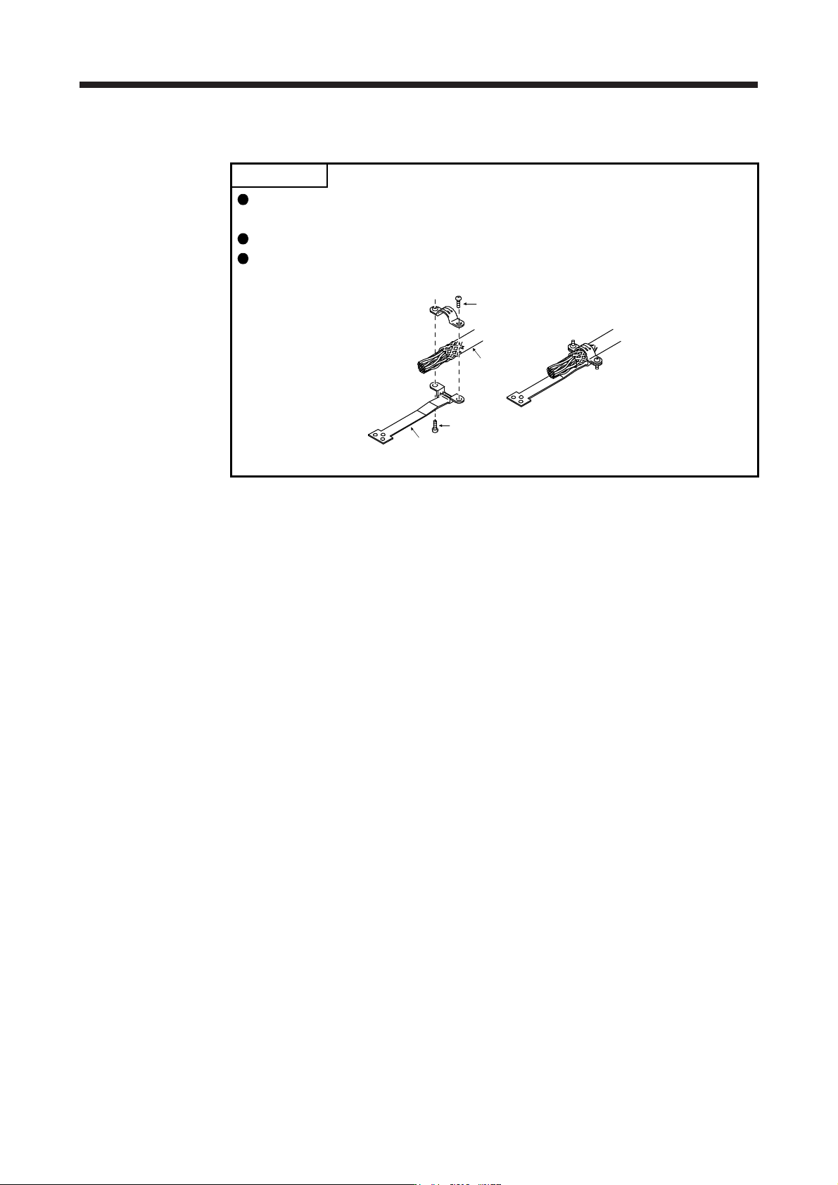
POINT
The pin assignment of the connectors is as viewed from the cable connector
wiring section.
For the STO I/O signal connector (CN8), refer to chapter 13.
For the CN3 connector, securely connect the external conductor of the shielded
cable to the ground plate and fix it to the connector shell.
Screw
Screw
Ground plate
Cable
3. SIGNALS AND WIRING
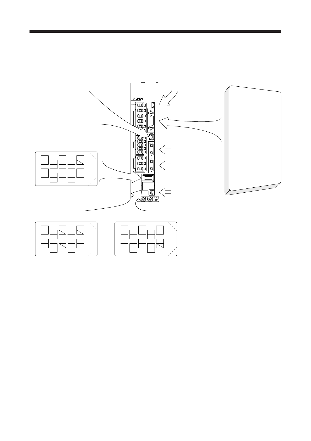
3 - 25
The servo amplifier front view shown is that of the MR-J4-20B or less. Refer to chapter 9 DIMENSIONS for
the appearances and connector layouts of the other servo amplifiers.
The frames of the CN2 and CN3 connectors are connected to the protective earth terminal in the servo
amplifier.
CN3
1
2
3
5
4
6
7
9
8
10
11
12
13
14
15
16
17
18
19
20
DI1
MO1
DICOM
LG
DOCOM
DICOM
LZ
DI2
MO2
EM2
LG
MBR
LBR
LA
LB
LZR
LAR
ALM
DI3INP
4
MRR
2
LG 8
6
1
P5
5
10
3
MR
7
9
BAT
MXR
MX
CN8
4
MRR2
2
LG 8
6
1
P5
5
10
3
MR2
7
9
MXR2
MX2
CN2L (Note 1, 2)
4
PAR
2
LG 8
6
1
P5
5
10
3
PA
7
9
PB
PZR
PZ
PBR PSEL
(for using serial encoder)
CN2L (Note 1, 2)
(for using A/B/Z-phase pulse encoder)
THM2
THM1
CN2 (Note 2)
CN5 (USB connector)
Refer to section 11.7
CN1A
Connector for SSCNET III
cable for previous servo
amplifier axis
CN1B
Connector for SSCNET III
cable for next servo
amplifier axis
CN4
(Battery connector)
Refer to section 11.8
For the STO I/O signal
connector, refer to section 13.2.
BAT
Note 1. The MR-J4-_B_ servo amplifiers have CN2L connectors. This CN2L is a connector of 3M.
When usin
g
an
y
other connector, refer to each servo motor instruction manual.
2. Refer to table 1.1 and "Linear Encoder Instruction Manual" for connections of external encoders.