sh030106u.pdf - 第221页
6. NORM AL GAIN ADJ USTMENT 6 - 20 6.3.3 Adjus tment proced ure by au to tuning Since aut o tuni ng is ena bled bef ore shipm ent from t he fac tory, simp ly runnin g the servo motor a utomat ically sets the o ptimum ga …
6. NORMAL GAIN ADJUSTMENT
6 - 19
6.3.2 Auto tuning mode basis
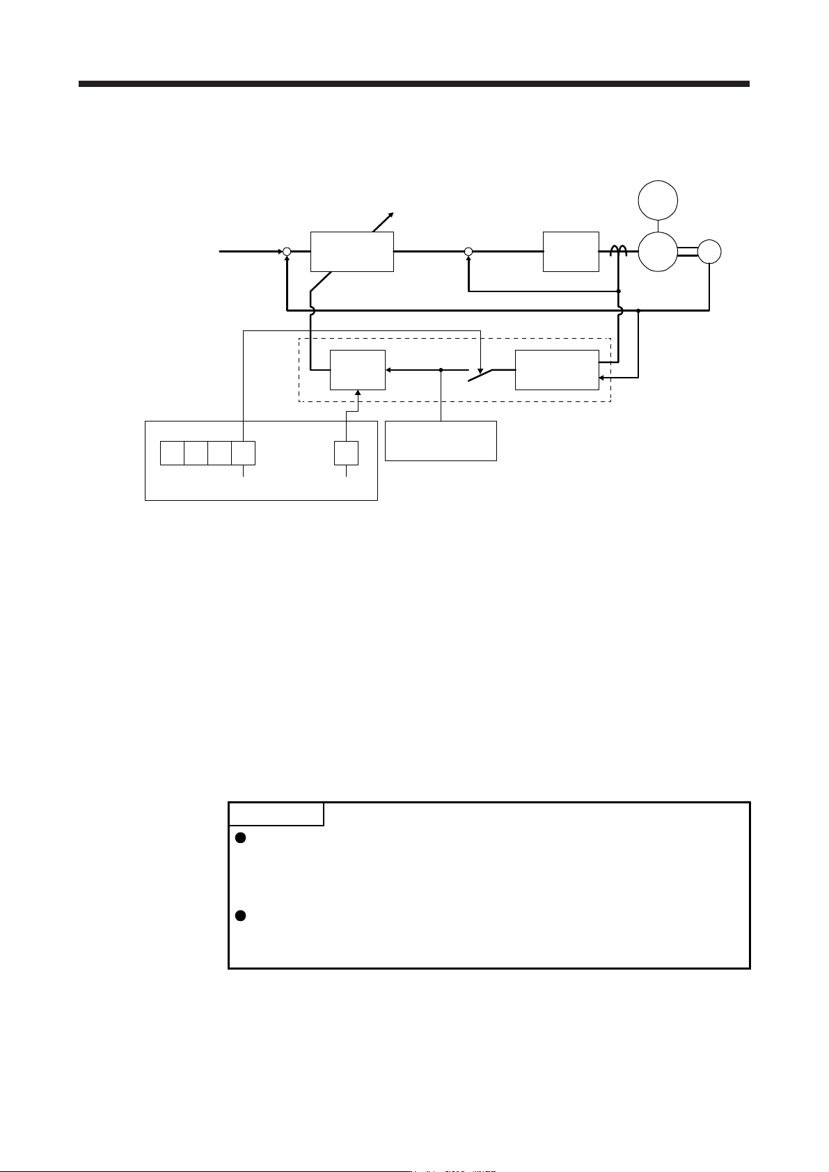
The block diagram of real-time auto tuning is shown below.
Loop gain
PG1, PG2,
VG2, VIC
Current
control
Load to motor
inertia ratio
estimation section
Gain table
[Pr. PB06 Load to
motor inertia ratio/
load to motor mass ratio]
Response
level setting
Gain adjustment mode selection
[Pr. PA08]
+
-
+
-
Real-time
auto tuning section
Set 0 or 1 to turn on.
Switch
Current feedback
Position/speed
feedback
Speed feedback
Load moment
of inertia
Encoder
Command
Automatic setting
[Pr. PA09]
M
Servo motor
000
When a servo motor is accelerated/decelerated, the load to motor inertia ratio estimation section always
estimates the load to motor inertia ratio from the current and speed of the servo motor. The results of
estimation are written to [Pr. PB06 Load to motor inertia ratio/load to motor mass ratio]. These results can be
confirmed on the status display screen of the MR Configurator2.
If you have already known the value of the load to motor inertia ratio or failed to estimate, set "Gain
adjustment mode selection" to "Auto tuning mode 2 (_ _ _ 2)" in [Pr. PA08] to stop the estimation (turning off
the switch in above diagram), and set the load to motor inertia ratio or load to motor mass ratio ([Pr. PB06])
manually.
From the preset load to motor inertia ratio ([Pr. PB06]) value and response ([Pr. PA09]), the optimum loop
gains are automatically set on the basis of the internal gain table.
The auto tuning results are saved in the EEP-ROM of the servo amplifier every 60 minutes since power-on.
At power-on, auto tuning is performed with the value of each loop gain saved in the EEP-ROM being used as
an initial value.
POINT
If sudden disturbance torque is imposed during operation, the load to motor
inertia ratio may be misestimated temporarily. In such a case, set "Gain
adjustment mode selection" to "Auto tuning mode 2 (_ _ _ 2)" in [Pr. PA08] and
then set the correct load to motor inertia ratio in [Pr. PB06].
When any of the auto tuning mode 1 and auto tuning mode settings is changed
to the manual mode 2 setting, the current loop gains and load to motor inertia
ratio estimation value are saved in the EEP-ROM.

6. NORMAL GAIN ADJUSTMENT
6 - 20
6.3.3 Adjustment procedure by auto tuning
Since auto tuning is enabled before shipment from the factory, simply running the servo motor automatically
sets the optimum gains that match the machine. Merely changing the response level setting value as
required completes the adjustment. The adjustment procedure is as follows.
Auto tuning adjustment
Acceleration/deceleration repeated
Auto tuning conditions
are not satisfied? (Estimation of
load to motor inertia ratio is
difficult.)
Load to motor inertia ratio
estimation value stable?
Set [Pr. PA08] to "_ _ _ 2" and set
[Pr. PB06 Load to motor inertia
ratio/load to motor mass ratio] manually.
Adjust response level setting so
that desired response is achieved
on vibration-free level.
To 2 gain adjustment
mode 2
Requested performance
satisfied?
End
Yes
No
Yes
No
No
Yes
Acceleration/deceleration repeated
6. NORMAL GAIN ADJUSTMENT
6 - 21
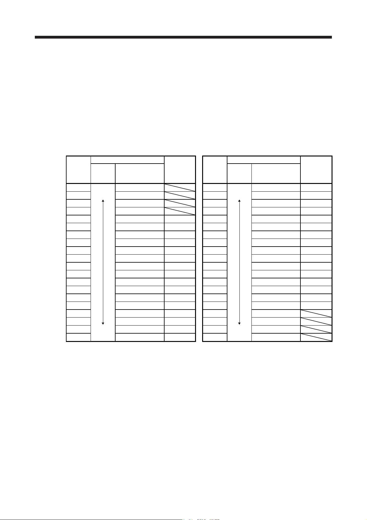
6.3.4 Response level setting in auto tuning mode
Set the response of the whole servo system by [Pr. PA09]. As the response level setting is increased, the
trackability to a command improves and settling time decreases, but setting the response level too high will
generate vibration. Set a value to obtain the desired response level within the vibration-free range.
If the response level setting cannot be increased up to the desired response because of machine resonance
beyond 100 Hz, filter tuning mode selection in [Pr. PB01] or machine resonance suppression filter in [Pr.
PB13] to [Pr. PB16], [Pr. PB46] to [Pr. PB51] may be used to suppress machine resonance. Suppressing
machine resonance may allow the response level setting to increase. Refer to section 7.2 and 7.3 for
settings of the adaptive tuning mode and machine resonance suppression filter.
[Pr. PA09]
Setting
value
Machine characteristic
Reference
(setting
value of
MR-J3)
Setting
value
Machine characteristic
Reference
(setting
value of
MR-J3)
Response
Guideline for
machine resonance
frequency [Hz]
Response
Guideline for
machine resonance
frequency [Hz]
1
Low
response
2.7 21
Middle
response
67.1
17
2 3.6 22 75.6
18
3
4.9 23
85.2
19
4 6.6 24 95.9
20
5 10.0
1
25 108.0
21
6 11.3
2
26 121.7
22
7 12.7
3
27 137.1
23
8 14.3
4
28 154.4
24
9 16.1
5
29 173.9
25
10 18.1
6
30 195.9
26
11 20.4
7
31 220.6
27
12 23.0
8
32 248.5
28
13 25.9
9
33 279.9
29
14 29.2
10
34 315.3
30
15 32.9
11
35 355.1
31
16 37.0
12
36 400.0
32
17 41.7
13
37 446.6
18 47.0
14
38 501.2
19
Middle
response
52.9
15
39
High
response
571.5
20 59.6
16
40 642.7