sh030106u.pdf - 第265页
7. SPEC IAL ADJUSTMEN T FUNCT IONS 7 - 36 (d) Adjust ing the l ost m otion co mpensatio n When protr usions st ill occ ur, the compe nsation is insu fficien t. Increas e the los t mot ion compe nsati on by approxi mately…

7. SPECIAL ADJUSTMENT FUNCTIONS
7 - 35
(d) Lost motion compensation timing ([Pr. PE49])
You can set the delay time of the lost motion compensation start timing with this parameter. When a
protrusion occurs belatedly, set the lost motion compensation timing corresponding to the protrusion
occurrence timing.
(e) Lost motion compensation non-sensitive band ([Pr. PE50])
When the travel direction reverses frequently around the zero speed, unnecessary lost motion
compensation is triggered by the travel direction switching. By setting the lost motion compensation
non-sensitive band, the speed is recognized as 0 when the fluctuation of the droop pulse is the
setting value or less. This prevents unnecessary lost motion compensation.
When the value of this parameter is changed, the compensation timing is changed. Adjust the value
of Lost motion compensation timing ([Pr. PE49]).
(f) Lost motion filter setting ([Pr. PE46])
Changing the value of this parameter is usually unnecessary. When a value other than 0.0 ms is set
in this parameter, the high-pass filter output value of the set time constant is applied to the
compensation and lost motion compensation continues.
(2) Adjustment procedure of the lost motion compensation function
(a) Measuring the load current
Measure the load currents during the forward direction feed and reverse direction feed with MR
Configurator2.
(b) Setting the lost motion compensation
Calculate the friction torque from the measurement result of (2) (a) in this section and set a value
twice the friction torque in [Pr. PE44] and [Pr. PE45] as lost motion compensation.
Friction torque [%] =
2
|(load current during feed in the forward rotation direction [%]) -
(load current during feed in the reverse rotation direction [%])|
(c) Checking protrusions
Drive the servo motor and check that the protrusions are corrected.
7. SPECIAL ADJUSTMENT FUNCTIONS
7 - 36
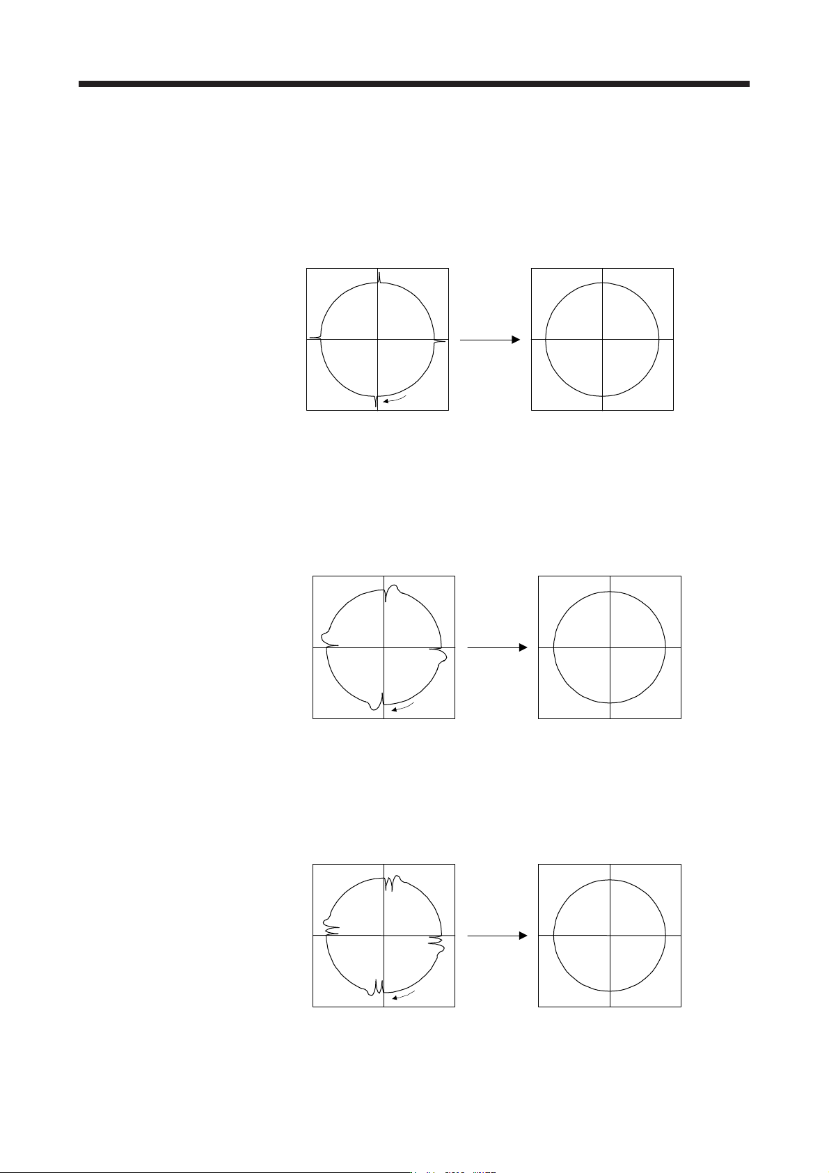
(d) Adjusting the lost motion compensation
When protrusions still occur, the compensation is insufficient. Increase the lost motion compensation
by approximately 0.5% until the protrusions are eliminated. When notches occur, the compensation
is excessive. Decrease the lost motion compensation by approximately 0.5% until the notches are
eliminated. Different values can be set as the compensation for each of when the forward rotation
(CCW) switches to the reverse rotation (CW) and when the reverse rotation (CW) switches to the
forward rotation (CCW).
The locus before compensation The locus after compensation
Compensation
Travel
direction
(e) Adjusting the lost motion compensation timing
When the machine has low rigidity, the speed loop gain is set lower than the standard setting value,
or the servo motor is rotating at high speed, quadrant projections may occur behind the quadrant
change points. In this case, you can suppress the quadrant projections by delaying the lost motion
compensation timing with [Pr. PE49 Lost motion compensation timing]. Increase the setting value of
[Pr. PE49] from 0 ms (Initial value) by approximately 0.5 ms to adjust the compensation timing.
Before timing delay compensation After timing delay compensation
Compensation
Travel
direction
(f) Adjusting the lost motion compensation non-sensitive band
When the lost motion is compensated twice around a quadrant change point, set [Pr. PE50 Lost
motion compensation non-sensitive band]. Increase the setting value so that the lost motion is not
compensated twice. Setting [Pr. PE50] may change the compensation timing. Adjust the lost motion
compensation timing of (2) (e) in this section.
Before timing delay compensation After timing delay compensation
Compensation
Travel
direction
7. SPECIAL ADJUSTMENT FUNCTIONS
7 - 37
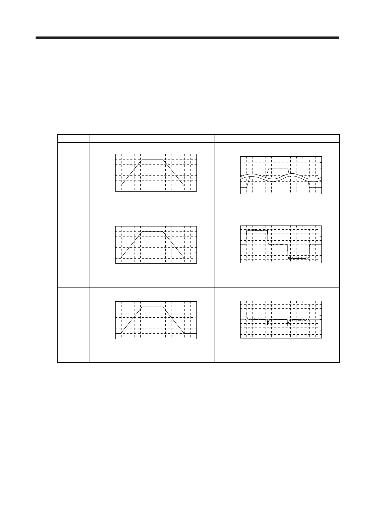
7.7 Super trace control
(1) Summary
In the normal position control, droop pulses are generated against the position control command from
the controller. Using the feed forward gain sets droop pulses at a constant speed to almost 0. However,
droop pulses generated during acceleration/deceleration cannot be suppressed.
With the ideal model in the servo amplifier, the super trace control enables to set constant speed and
uniform acceleration/deceleration droop pulses to almost 0 that cannot be coped with by the feed
forward gain.
Control Position command (the same command) Droop pulses
Normal
control
Time
Servo motor speed
Time
Droop pulses
Droop pulses are always generated.
Feed
forward gain
Time
Servo motor speed
Time
Droop pulses
Droop pulses are generated during acceleration/
deceleration.
Super trace
control
Time
Servo motor speed
Time
Droop pulses
Droop pulses are almost 0 including the time of
acceleration or deceleration.