sh030106u.pdf - 第641页
APPENDIX App. - 10 (2) Connectio n exampl e ST O1 4 5 3 6 7 8 CN3 EM 2 (B-ax is) CN8 SDO1A+ 4A 4B SDO1 A- SDI1 A+ 1A 1B SDI 1A- SDI2 A+ SRESA+ SDO2A+ TOFA 3A 3B 1A 1B 6A 6B 8A SDI2A- SDO2 A- SRESA- CN9 CN10 STO1 TOFB2 TO…
APPENDIX
App. - 9
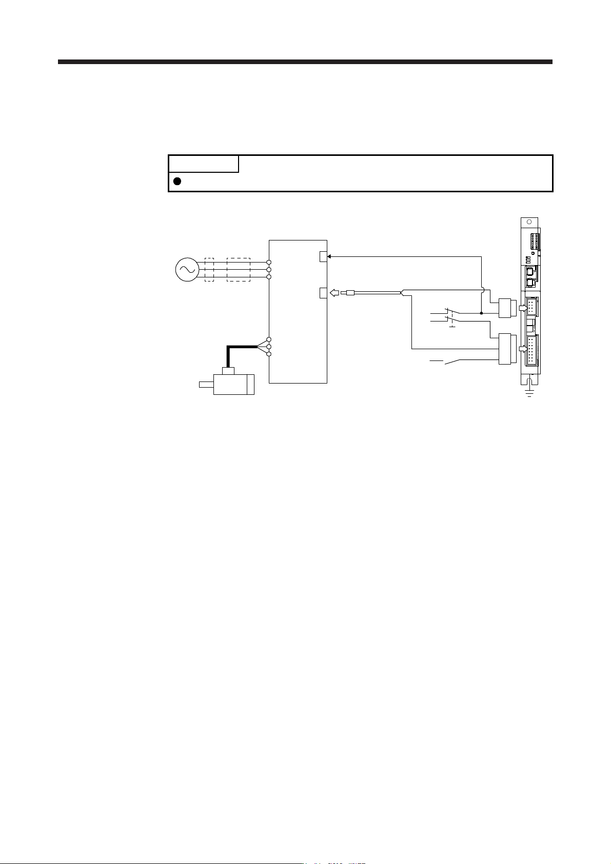
App. 5.7.3 When using MR-J3-D05 with an MR-J4 series servo amplifier
(1) System configuration diagram
The following shows the connection targets of the STO switch and STO release switch.
POINT
MR-D05UDL_M (STO cable) for MR-J3 series cannot be used.
MR-J3-D05
FG
STO switch
STO release switch
Magnetic
contactor
MCCB
Power
supply
Servo motor
MR-J4_B_(-RJ)
STO cable
MR-D05UDL3M-B
CN9
CN10
CN8
CN3
L1
L2
L3
U
V
W
EM2 (Forced stop 2)
APPENDIX
App. - 10
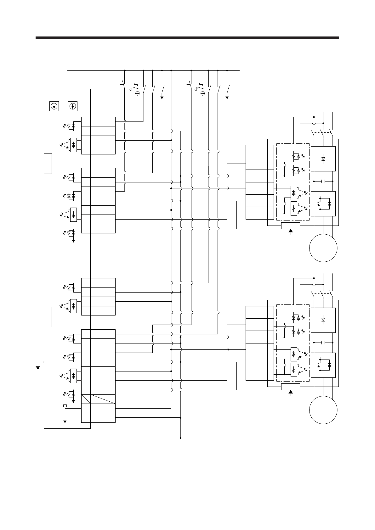
(2) Connection example
STO1
4
5
3
6
7
8
CN3
EM2 (B-axis)
CN8
SDO1A+4A
4B SDO1A-
SDI1A+1A
1B SDI1A-
SDI2A+
SRESA+
SDO2A+
TOFA
3A
3B
1A
1B
6A
6B
8A
SDI2A-
SDO2A-
SRESA-
CN9
CN10
STO1
TOFB2
TOFCOM
STO2
STOCOM
TOFB1
MR-J4_B_(-RJ)
FG
4
5
3
6
7
8
CN3
EM2 (A-axis)
CN8
TOFB2
TOFCOM
STO2
STOCOM
TOFB1
MR-J4_B_(-RJ)
SDO1B+3A
3B SDO1B-
SDI1B+2A
2B SDI1B-
SDI2B+
SRESB+
SDO2B+
TOFB
4A
4B
2A
2B
5A
5B
8B
+24V7A
0V7B
SDI2B-
SDO2B-
SRESB-
CN9
CN10
MR-J3-D05
S1
24 V
0 V
STOA
S3
STOB
MC
M
Servo motor
MC
M
Servo motor
Control circuit
Control circuit
CN8A
CN8B
EM2
(A-axis)
EM2
(B-axis)
SW1 SW2
(Note 1) (Note 1)
(Note 2) (Note 2)
RESA RESB
S4
S2
Note 1. Set the delay time of STO output with SW1 and SW2. These switches are located in a recessed area to prevent accidental
settin
g
chan
g
es.
2. To release the STO state
(
base circuit shut-off
)
, turn RESA and RESB on and turn them off.
APPENDIX
App. - 11
App. 5.8 Signal
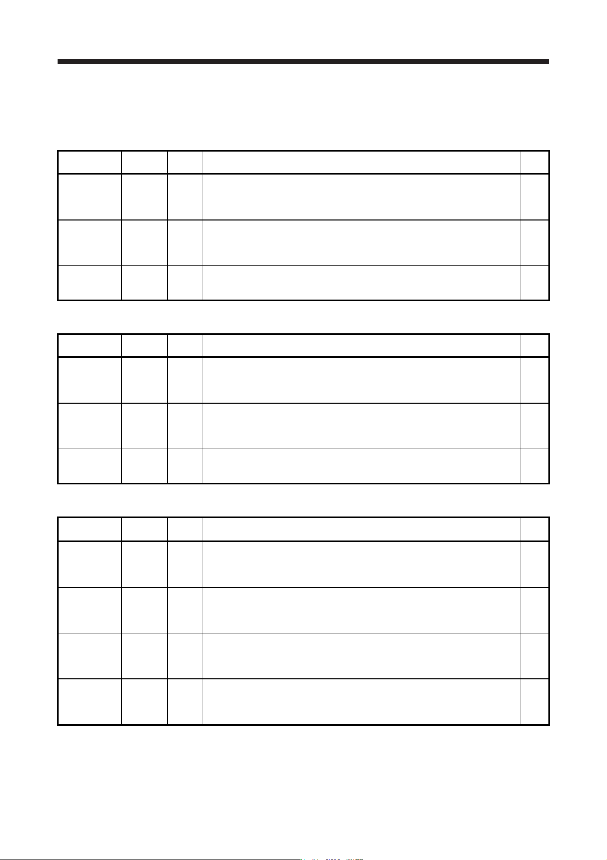
App. 5.8.1 Connector/pin assignment
(1) CN8A
Device Symbol Pin No. Function/application
I/O
division
A-axis STO1 STO1A-
STO1A+
1
4
Outputs STO1 to A-axis driving device.
Outputs the same signal as A-axis STO2.
STO state (base shutdown): Between STO1A+ and STO1A- is opened.
STO release state (in driving): Between STO1A+ and STO1A- is closed.
O
A-axis STO2 STO2A-
STO2A+
5
6
Outputs STO2 to A-axis driving device.
Outputs the same signal as A-axis STO1.
STO state (base shutdown): Between STO2A+ and STO2A- is opened.
STO release state (in driving): Between STO2A+ and STO2A- is closed.
O
A-axis STO
state
TOF2A
TOF1A
7
8
Inputs STO state of A-axis driving device.
STO state (base shutdown): Open between TOF2A and TOF1A.
STO release state (in driving): Close between TOF2A and TOF1A.
I
(2) CN8B
Device Symbol Pin No. Function/application
I/O
division
B-axis STO1 STO1B-
STO1B+
1
4
Outputs STO1 to B-axis driving device.
Outputs the same signal as B-axis STO2.
STO state (base shutdown): Between STO1B+ and STO1B- is opened.
STO release state (in driving): Between STO1B+ and STO1B- is closed.
O
B-axis STO2 STO2B-
STO2B+
5
6
Outputs STO2 to B-axis driving device.
Outputs the same signal as B-axis STO1.
STO state (base shutdown): Between STO2B+ and STO2B- is opened.
STO release state (in driving): Between STO2B+ and STO2B- is closed.
O
B-axis STO
state
TOF2B
TOF1B
7
8
Inputs STO state of B-axis driving device.
STO state (base shutdown): Open between TOF2B and TOF1B.
STO release state (in driving): Close between TOF2B and TOF1B.
I
(3) CN9
Device Symbol Pin No. Function/application
I/O
division
A-axis
shutdown 1
SDI1A+
SDI1A-
1A
1B
Connect this device to a safety switch for A-axis driving device.
Input the same signal as A-axis shutdown 2.
STO state (base shutdown): Open between SDI1A+ and SDI1A-.
STO release state (in driving): Close between SDI1A+ and SDI1A-.
DI-1
B-axis
shutdown 1
SDI1B+
SDI1B-
2A
2B
Connect this device to a safety switch for B-axis driving device.
Input the same signal as B-axis shutdown 2.
STO state (base shutdown): Open between SDI1B+ and SDI1B-.
STO release state (in driving): Close between SDI1B+ and SDI1B-.
DI-1
A-axis SDO1 SDO1A+
SDO1A-
4A
4B
Outputs STO1 to A-axis driving device.
Outputs the same signal as A-axis SDO2.
STO state (base shutdown): Between SDO1A+ and SDO1A- is opened.
STO release state (in driving): Between SDO1A+ and SDO1A- is closed.
DO-1
B-axis SDO1 SDO1B+
SDO1B-
3A
3B
Outputs STO1 to B-axis driving device.
Outputs the same signal as B-axis SDO2.
STO state (base shutdown): Between SDO1B+ and SDO1B- is opened.
STO release state (in driving): Between SDO1B+ and SDO1B- is closed.
DO-1