sh030106u.pdf - 第467页
13. USIN G STO FUNCTI ON 13 - 14 13.4.2 Sourc e I/O int erface In this serv o amplifi er, sourc e type I/O interfaces c an be used . (1) Digital i nput in terface D I-1 This is a n input circ uit whos e photoc oupler ano…
13. USING STO FUNCTION
13 - 13
(b) When outputting two STO states by using one TOFB
If polarity of diode is
reversed, servo amplifier
will malfunction.
TOFCOM
Servo amplifier
TOFB2
LoadTOFB1
(Note)
24 V DC ± 10%
300 mA
Note. If the voltage drop (maximum of 5.2 V) interferes with the relay operation, apply high
volta
g
e
(
maximum of 26.4 V
)
from external source.
13. USING STO FUNCTION
13 - 14
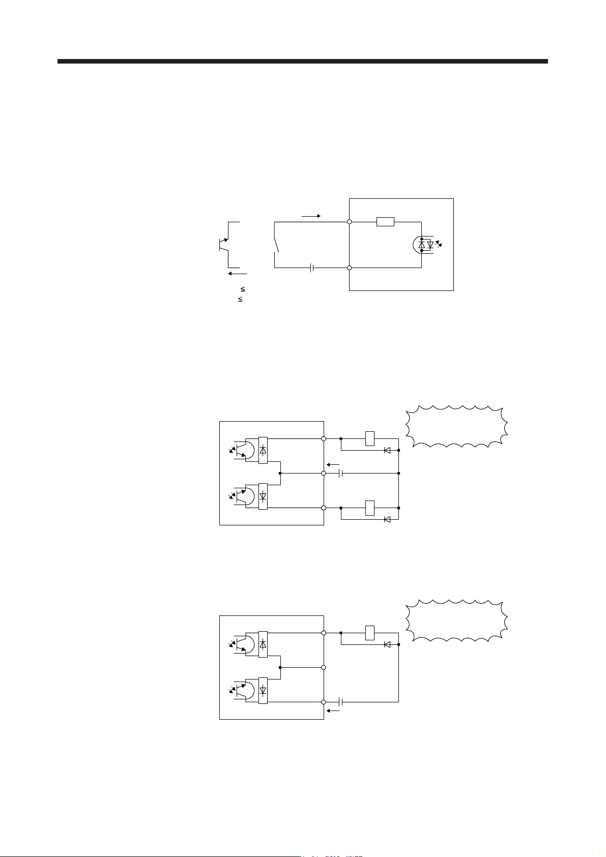
13.4.2 Source I/O interface
In this servo amplifier, source type I/O interfaces can be used.
(1) Digital input interface DI-1
This is an input circuit whose photocoupler anode side is the input terminal. Transmit signals from source
(open-collector) type transistor output, relay switch, etc.
Approx. 3.0 kΩ
STO1
STO2
Servo amplifier
Switch
STOCOM
TR
Approx. 5 mA
V
CES
1.0 V
I
CEO
100 µA
24 V DC ± 10%
300 mA
(2) Digital output interface DO-1
This is a circuit in which the emitter of the output transistor is the output terminal. When the output
transistor is turned on, current will be applied from the output to a load.
A maximum of 5.2 V voltage drop occurs in the servo amplifier.
(a) When outputting two STO states by using each TOFB
Servo amplifier
Load
(Note)
24 V DC ± 10%
300 mA
TOFCOM
TOFB2
TOFB1
Load
If polarity of diode is
reversed, servo amplifier
will malfunction.
Note. If the voltage drop (maximum of 2.6 V) interferes with the relay operation, apply high
volta
g
e
(
maximum of 26.4 V
)
from external source.
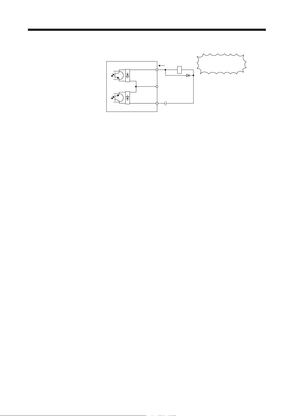
(b) When outputting two STO states by using one TOFB
Servo amplifier
Load
(Note)
24 V DC ± 10%
300 mA
TOFCOM
TOFB2
TOFB1
If polarity of diode is
reversed, servo amplifier
will malfunction.
Note. If the voltage drop (maximum of 5.2 V) interferes with the relay operation, apply high
volta
g
e
(
maximum of 26.4 V
)
from external source.
14. USING A LINEAR SERVO MOTOR
14 - 1
14. USING A LINEAR SERVO MOTOR
WARNING
When using the linear servo motor, read "Linear Servo Motor Instruction Manual"
and "Linear Encoder Instruction Manual".
14.1 Functions and configuration
14.1.1 Summary
The fields of semiconductor/LCD manufacturing systems, mounters, and others have strong demands for
high accuracy, high speed, and efficiency. Therefore, the number of systems using a linear servo motor for a
drive axis has been increasing. Using a linear servo system can achieve higher speed and
acceleration/deceleration characteristics than the ball screw-drive system. Unlike the ball screw-drive
system, the linear servo system does not have disadvantages such as ball screw wear. The linear servo
system allows the service life of equipment to be prolonged. In addition, since a response error due to
backlash and friction does not occur, you can establish a high-accuracy system.
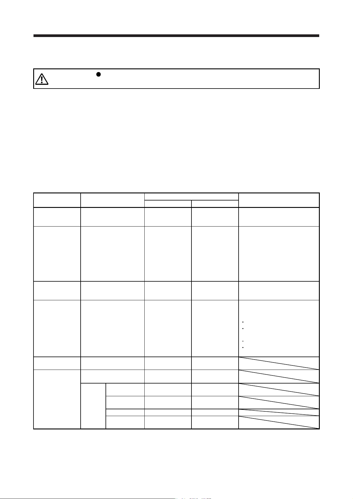
The following shows the differences between the linear servo motor and the rotary servo motor.
Category Item
Differences
Remark
Linear servo motor Rotary servo motor
External I/O signal
FLS (Upper stroke limit),
RLS (Lower stroke limit)
Required (for
magnetic pole
detection)
Not required
Automatically turns on in the
parameter setting.
Motor pole
adjustment
Magnetic pole detection Required Not required
(default setting)
Automatically executed at the first
servo-on after the power is turned
on.
For the absolute position linear
encoder, [Pr. PL01] can disable the
magnetic pole detection. The timing
of the magnetic pole detection can
be changed with [Pr. PL01]. (Refer
to (2) (b) of section 14.3.3.)
Home position
return
Reference home position 1048576 pulses unit
(initial value)
One servo motor
revolution unit
Home position return pitch can be
changed with parameter setting.
(Refer to section 14.3.3)
Absolute position
detection system
Absolute position encoder
battery
Not required Required
The following alarms and warnings
are not provided for the linear servo
motor.
[AL. 25 Absolute position erased]
[AL. 92 Battery cable
disconnection warning]
[AL. 9F Battery warning]
[AL. E3 Absolute position counter
warning]
Auto tuning
Load to motor inertia ratio
(J)
Load to motor mass
ratio
Load to motor
inertia ratio
MR Configurator2
(SW1DNC-MRC2-_)
Motor speed
(Data display and setting)
mm/s unit r/min unit
(Software version
1.19V or later)
Test
operation
function
Positioning
operation
Supported Supported
Motor-less
operation
None Supported
JOG operation None Supported
Program
operation
Supported Supported