sh030106u.pdf - 第480页
14. USIN G A LINEAR SER VO MOTOR 14 - 13 (b) Magnetic pole d etecti on by the m inute position detec tion me thod Is the tr avel di stance during the magnetic pole detection acceptable? (Note 3) 1) Check that FLS (U pper…

14. USING A LINEAR SERVO MOTOR
14 - 12
(1) Magnetic pole detection method by using MR Configurator2
The following shows the magnetic pole detection procedure by using MR Configurator2.
(a) Magnetic pole detection by the position detection method
Have [AL. 32 Overcurrent], [AL. 50
Overload 1], [AL. 51 Overload 2], and
[AL. E1 Overload warning 1]
occurred?
1) Check that FLS (Upper stroke limit), RLS (Lower stroke limit), and EM2 (Forced stop 2) are on, and
then cycle the servo amplifier power.
Turn "On (up)" the test operation select switch (SW2-1) of the servo amplifier, and then cycle the
power of the servo amplifier.
Set [Pr. PL08 Linear servo motor/DD motor function selection 3] to "_ _ _ 0" to set the magnetic
pole detection method to "Position detection method".
Cycle the servo amplifier power.
6) Set [Pr. PL09 Magnetic pole detection voltage level] to "10".
7) Execute "Positive direction travel" or "Negative direction travel" with "Positioning operation" in the
test operation mode on MR Configurator2. Set the travel distance to "0" at this time.
8)
Set [Pr. PL01] to "_ _ _ 0" to set "Magnetic pole detection disabled". (Note)
2)
3)
4)
5)
The magnetic pole detection is carried out.
Is [Pr. PL09] the final value?
Has [AL. 27 Initial magnetic pole
detection error] occurred?
Reset the alarm or cycle the
servo amplifier power.
Cycle the servo amplifier power.
Reset the alarm or cycle the
servo amplifier power.
Increase the value of [Pr. PL09]
by five.
Set an approximately 70% of the
value set for [Pr. PL09] as the
final setting value.
If [AL. 27 Initial magnetic pole
detection error] occurs with this
value, specify a value
intermediate between the value
set at [AL. E1 Overload warning
1] and the value set at [AL. 27
Initial magnetic pole detection
error] as the final setting value.
NO
YES
YES
NO
YES
NO
Magnetic pole detection
End
Set [Pr. PL01 Linear servo motor/DD motor function selection 1] to "_ _ _ 1" to enable "Magnetic
pole detection at first servo-on". (Note)
Note. For the incremental s
y
stem, the [Pr. PL01] settin
g
is not required.

14. USING A LINEAR SERVO MOTOR
14 - 13
(b) Magnetic pole detection by the minute position detection method
Is the travel distance during
the magnetic pole detection
acceptable? (Note 3)
1) Check that FLS (Upper stroke limit), RLS (Lower stroke limit), and EM2 (Forced stop 2) are on, and
then cycle the servo amplifier power.
Turn "On (up)" the test operation select switch (SW2-1) of the servo amplifier, and then cycle the
power of the servo amplifier.
Set [Pr. PL08 Linear servo motor/DD motor function selection 3] to "_ _ _ 4" to set the magnetic
pole detection method to "Minute position detection method".
Cycle the servo amplifier power.
6) With [Pr. PL17 Magnetic pole detection - Minute position detection method - Function selection],
set the load to mass of the linear servo motor primary-side ratio. (Note 2)
7) Execute "Positive direction travel" or "Negative direction travel" with "Positioning operation" in the
test operation mode on MR Configurator2. Set the travel distance to "0" at this time.
8)
Set [Pr. PL01] to "_ _ _ 0" to set "Magnetic pole detection disabled". (Note 1)
2)
3)
4)
5)
The magnetic pole detection is carried out.
Is "Response selection"
of [Pr. PL17] set to a final
setting value?
Has an abnormal sound or
vibration occurred during the
magnetic pole detection?
Decrease the value set in "Response
selection" of [Pr. PL17] by two.
Increase the value set in "Response
selection" of [Pr. PL17] by one.
Not
acceptable
YES
Acceptable
NO
YES
NO
Magnetic pole detection
End
Set [Pr. PL01 Linear servo motor/DD motor function selection 1] to "_ _ _ 1" to enable "Magnetic
pole detection at first servo-on". (Note 1)
Note 1. When the linear encoder is an incremental t
y
pe, the [Pr. PL01] settin
g
is not required.
2. If the load to primary-side linear servo motor mass ratio is unknown, perform the magnetic pole
detection b
y
the position detection method, and then perform the auto tunin
g
to set an estimated value.
3. For the magnetic pole detection by the minute position detection method, the maximum travel distance
at the magnetic pole detection must be 0.5 mm or less. To shorten the travel distance, increase the
value of "Response selection" in [Pr. PL17].
14. USING A LINEAR SERVO MOTOR
14 - 14
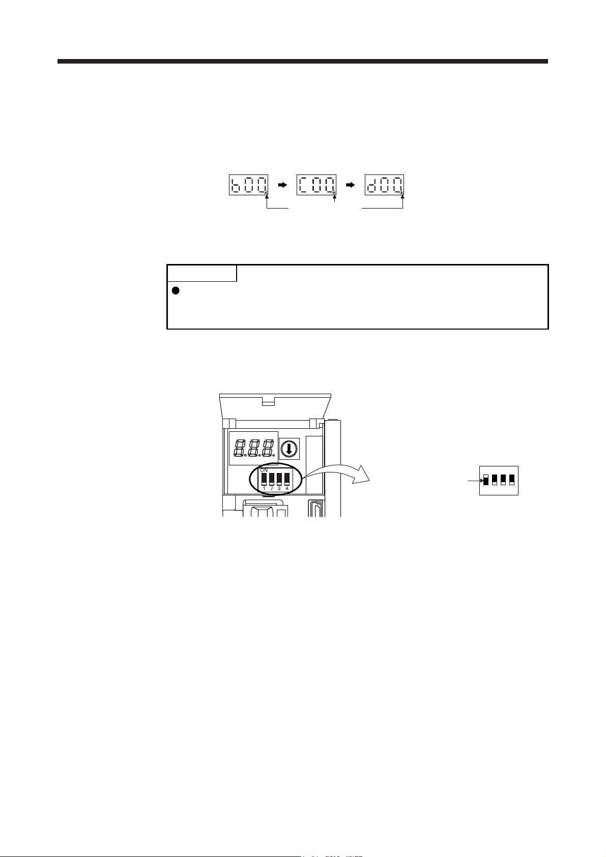
(c) State transition of the servo amplifier display (3-digit, 7-segment LED) at the magnetic pole detection
When the magnetic pole detection with MR Configurator2 is normally executed, the servo amplifier
display (3-digit, 7-segment LED) shows the state as below.
The decimal point
blinks.
Servo-off status
During the
magnetic pole
detection
Magnetic pole
detection
completion
(servo-on status)
(2) Preparation for the magnetic pole detection
POINT
When the test operation mode is selected with the test operation select switch
(SW2-1), the SSCNET III/H communication for the servo amplifier in the test
operation mode and the following servo amplifiers is blocked.
For the magnetic pole detection, use the test operation mode (positioning operation) of MR
Configurator2. Turn off the servo amplifier power, and set the test operation select switch (SW2-1) as
shown below. Turning on the power enables the test operation mode.
Set SW2-1 to "ON (up)".
1
ON
2 3 4