sh030106u.pdf - 第465页
13. USIN G STO FUNCTI ON 13 - 12 13.4 Deta iled des cription of int erfaces This sectio n provides the d etails of the I/O s ignal in terfaces (refer to the I/O divis io n in the table) giv en in section 13.2. Ref er to …
13. USING STO FUNCTION
13 - 11
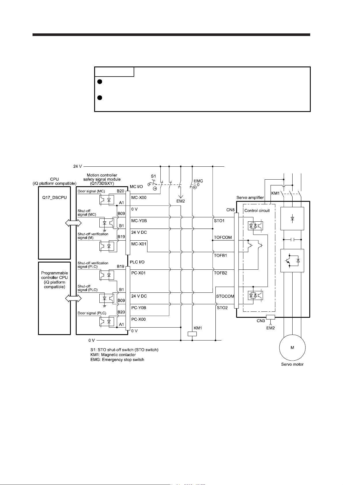
13.3.4 External I/O signal connection example using a motion controller
POINT
This connection is for source interface. For the other I/O signals, refer to the
connection examples in section 3.2.2.
For MC-Y0B and PC-Y0B, design a sequence program to output MC-Y0B and
PC-Y0B after the servo motor stops.
This connection diagram is an example of STO circuit configured with a servo amplifier and motion controller.
Use the switch that complies with the requirement of ISO/EN ISO 13849-1:2015 Category 3 PL d as an
emergency stop switch. This connection example complies with the requirement of ISO/EN ISO 13849-
1:2015 Category 3 PL d. The following shows an example of I/O (X and Y) signal assignment of the motion
controller safety signal module. For details, refer to the motion controller user’s manual.
13. USING STO FUNCTION
13 - 12
13.4 Detailed description of interfaces
This section provides the details of the I/O signal interfaces (refer to the I/O division in the table) given in
section 13.2. Refer to this section and make connection with the external device.
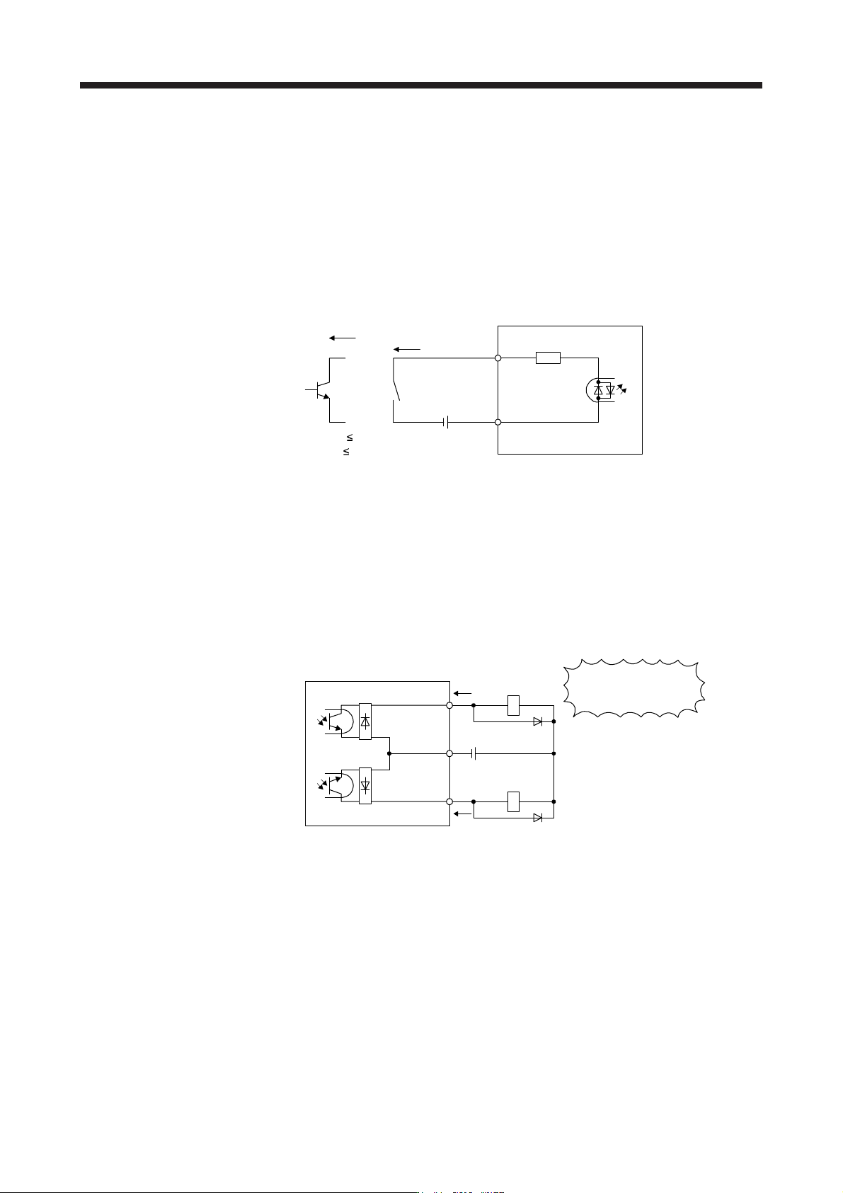
13.4.1 Sink I/O interface
(1) Digital input interface DI-1
This is an input circuit whose photocoupler cathode side is the input terminal. Transmit signals from sink
(open-collector) type transistor output, relay switch, etc.
Approx. 3.0 kΩ
STO1
STO2
Servo amplifier
Switch
Approx. 5 mA
For transistor
STOCOM
TR
V
CES
1.0 V
I
CEO
100 µA
24 V DC ± 10%
300 mA
(2) Digital output interface DO-1
This is a circuit in which the collector of the output transistor is the output terminal. When the output
transistor is turned on, the current will flow to the collector terminal.
A lamp, relay or photocoupler can be driven. Install a diode (D) for an inductive load, or install an inrush
current suppressing resistor (R) for a lamp load.
(Rated current: 40 mA or less, maximum current: 50 mA or less, inrush current: 100 mA or less) A
maximum of 5.2 V voltage drop occurs in the servo amplifier.
(a) When outputting two STO states by using each TOFB
TOFCOM
Servo amplifier
TOFB2
If polarity of diode is
reversed, servo amplifier
will malfunction.
LoadTOFB1
Load
(Note)
24 V DC ± 10%
300 mA
Note. If the voltage drop (maximum of 2.6 V) interferes with the relay operation, apply high
volta
g
e
(
maximum of 26.4 V
)
from external source.
13. USING STO FUNCTION
13 - 13
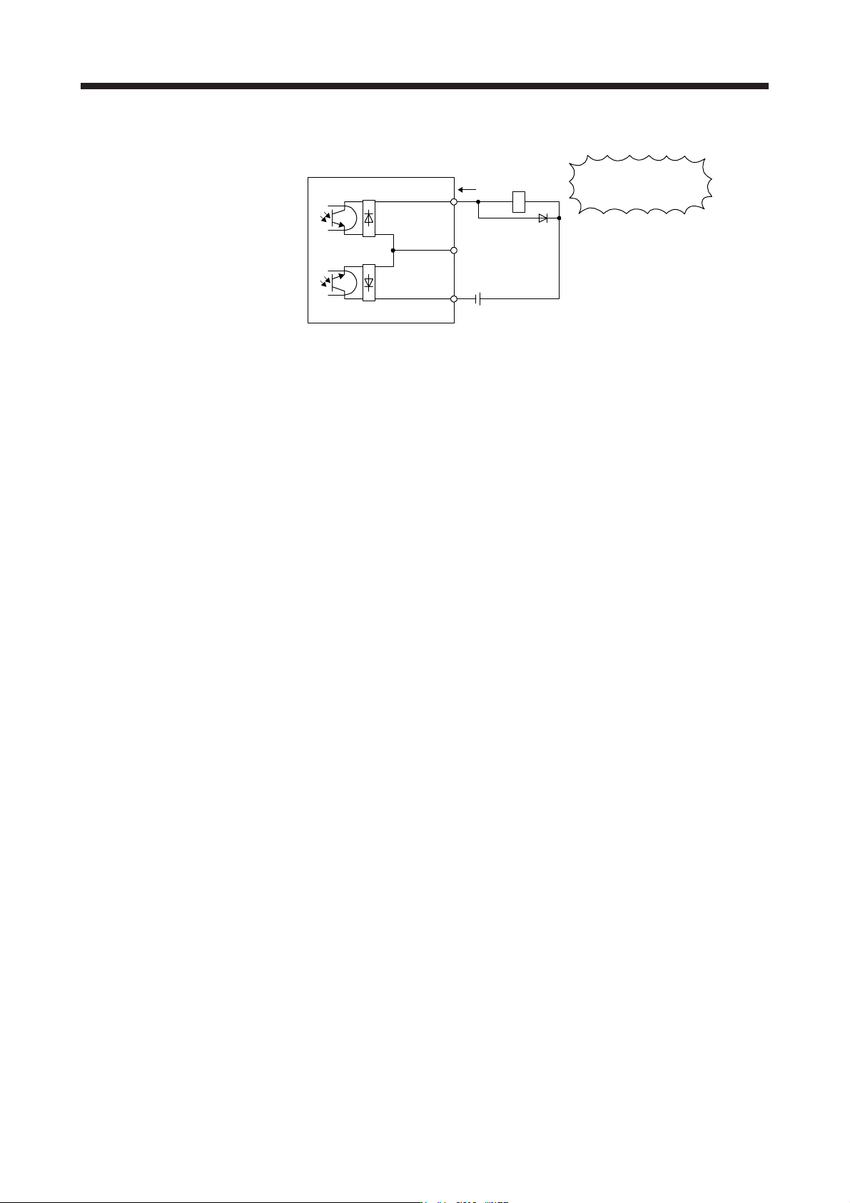
(b) When outputting two STO states by using one TOFB
If polarity of diode is
reversed, servo amplifier
will malfunction.
TOFCOM
Servo amplifier
TOFB2
LoadTOFB1
(Note)
24 V DC ± 10%
300 mA
Note. If the voltage drop (maximum of 5.2 V) interferes with the relay operation, apply high
volta
g
e
(
maximum of 26.4 V
)
from external source.