sh030106u.pdf - 第135页
4. STA RTUP 4 - 10 (c) Switch comb ination list f or the c ontrol ax is No. s etting POINT Set contro l axis Nos. fo r one system. For detail s of th e cont ro l axis No., refer t o the servo system controlle r user&apos…
4. STARTUP
4 - 9
(2) Disabling control axis switch (SW2-2)
Turning "ON (up)" the disabling control axis switch disables the corresponding servo motor. The servo
motor will be disabled-axis status and will not be recognized by the controller.
Disabling control axis switch
1
ON
2 3 4
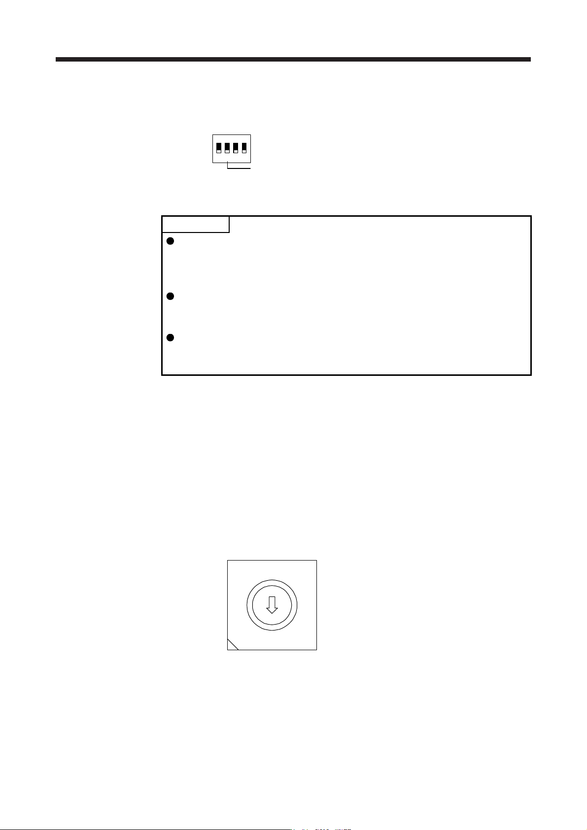
(3) Switches for setting control axis No.
POINT
The control axis No. set to the auxiliary axis number setting switches (SW2-3
and SW2-4) and the axis selection rotary switch (SW1) should be the same as
the one set to the servo system controller. The number of the axes you can set
depends on the servo system controller.
For setting the axis selection rotary switch, use a flat-blade screwdriver with the
blade edge width of 2.1 mm to 2.3 mm and the blade edge thickness of 0.6 mm
to 0.7 mm.
When the test operation mode is selected with the test operation select switch
(SW2-1), the SSCNET III/H communication for the servo amplifier in the test
operation mode and the following servo amplifiers is blocked.
You can set the control axis No. between 1 and 64 by using auxiliary axis number setting switches with
the axis selection rotary switch. (Refer to (3) (c) in this section.)
If the same numbers are set to different control axes in a single communication system, the system will
not operate properly. The control axes may be set independently of the SSCNET III cable connection
sequence. The following shows the description of each switch.
(a) Auxiliary axis number setting switches (SW2-3 and SW2-4)
Turning these switches "ON (up)" enables you to set the axis No. 17 or more.
(b) Axis selection rotary switch (SW1)
You can set the control axis No. between 1 and 64 by using auxiliary axis number setting switches
with the axis selection rotary switch. (Refer to (3) (c) in this section.)
8
7
6
5
4
3
2
1
0
F
E
D
C
B
A
9
A
xis selection rotary switch (SW1)
4. STARTUP
4 - 10
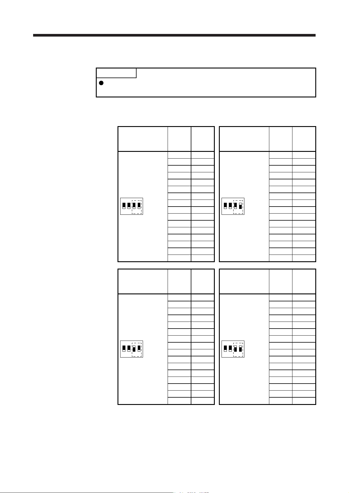
(c) Switch combination list for the control axis No. setting
POINT
Set control axis Nos. for one system. For details of the control axis No., refer to
the servo system controller user's manual.
The following lists show the setting combinations of the auxiliary axis number setting switches and
the axis selection rotary switch.
Auxiliary axis number
setting switch
Axis
selection
rotary
switch
Control
axis No.
Auxiliary axis number
setting switch
Axis
selection
rotary
switch
Control
axis No.
1
ON
2 3 4
0 1
1
ON
2 3 4
0 17
1 2 1 18
2 3 2 19
3 4 3 20
4 5 4 21
5 6 5 22
6 7 6 23
7 8 7 24
8 9 8 25
9 10 9 26
A 11 A 27
B 12 B 28
C 13 C 29
D 14 D 30
E 15 E 31
F 16 F 32
Auxiliary axis number
setting switch
Axis
selection
rotary
switch
Control
axis No.
Auxiliary axis number
setting switch
Axis
selection
rotary
switch
Control
axis No.
1
ON
2 3 4
0 33
1
ON
2 3 4
0 49
1 34 1 50
2 35 2 51
3 36 3 52
4 37 4 53
5 38 5 54
6 39 6 55
7 40 7 56
8 41 8 57
9 42 9 58
A 43 A 59
B 44 B 60
C 45 C 61
D 46 D 62
E 47 E 63
F 48 F 64
4. STARTUP
4 - 11
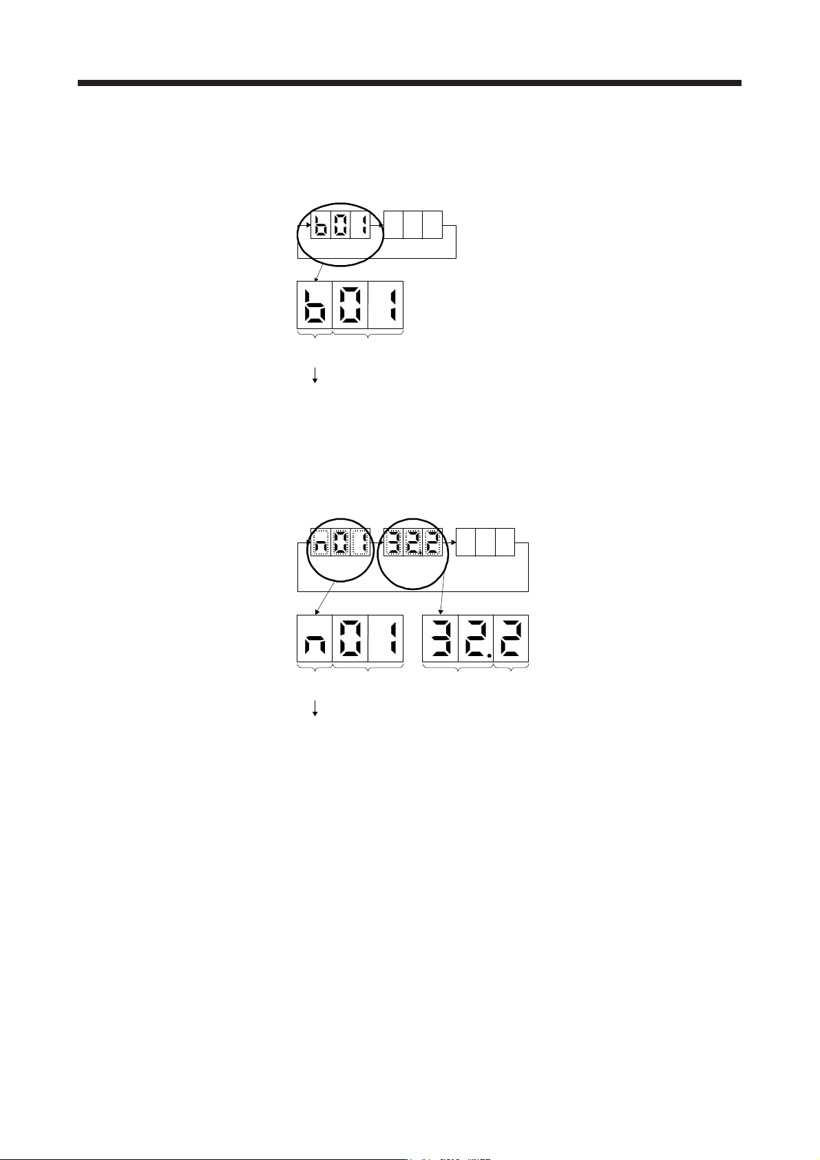
4.3.2 Scrolling display
(1) Normal display
When there is no alarm, the axis No. and blank are displayed in rotation.
Status
(1 digit)
Axis No.
(2 digits)
"b"
"C"
"d"
: Indicates ready-off and servo-off status.
: Indicates ready-on and servo-off status.
: Indicates ready-on and servo-on status.
Status
A
fter 1.6 s
Blank
After 0.2 s
(2) Alarm display
When an alarm occurs, the alarm number (two digits) and the alarm detail (one digit) are displayed
following the status display. For example, the following shows when [AL. 32 Overcurrent] is occurring.
Status
After 0.8 s
Alarm No.
After 0.8 s
Blank
After 0.2 s
Status
(1 digit)
Axis No.
(2 digits)
"n": Indicates that an alarm is occurring.
Alarm detail
(1 digit)
Alarm No.
(2 digits)