sh030106u.pdf - 第312页
10. CHA RACT ERISTI CS 10 - 7 (2) Heat diss ipation are a for an enclos ed type cabinet The enc losed ty pe cabin et (her eafter c alled t he cabin et) which w ill con tain the s erv o amplif ier sh ould be designed to e…
10. CHARACTERISTICS
10 - 6
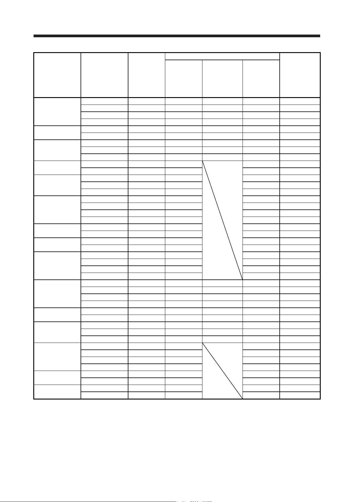
Servo amplifier Servo motor
Power supply
capacity
[kVA]
(Note 1)
Servo amplifier-generated heat [W] (Note 2)
Area required for
heat dissipation
[m
2
]
At rated output
At rated output
[Generated heat
in the cabinet
when cooled
outside the
cabinet] (Note 3)
With servo-off
MR-J4-11KB(-RJ)
HG-JR903 13 435 130 45 8.7
HG-JR11K1M 16 530 160 45 11.0
HG-JR801 12 370 110 45 7.0
HG-JR12K1 18 570 170 45 11.5
MR-J4-15KB(-RJ)
HG-JR15K1M 22 640 195 45 13.0
HG-JR15K1 22 640 195 45 12.8
MR-J4-22KB(-RJ)
HG-JR22K1M 33 850 260 55 17.0
HG-JR20K1 30 800 240 55 16.0
HG-JR25K1 38 900 270 55 19.0
MR-J4-60B4(-RJ)
HG-SR524 1.0 40
18 0.8
HG-JR534 1.0 40 18 0.8
HG-SR1024 1.7 60 18 1.2
MR-J4-100B4(-RJ) HG-JR734 1.3 60 18 1.2
HG-JR1034 1.7 60 18 1.2
HG-SR1524 2.5 90 20 1.8
MR-J4-200B4(-RJ)
HG-SR2024 3.5 90 20 1.8
HG-JR1534 2.5 90 20 1.8
HG-JR2034 3.5 90 20 1.8
MR-J4-350B4(-RJ)
HG-SR3524 5.5 130 20 2.6
HG-JR3534 5.5 160 20 2.7
MR-J4-500B4(-RJ)
HG-SR5024 7.5 195 25 3.9
HG-JR5034 7.5 195 25 3.9
MR-J4-700B4(-RJ)
HG-SR7024 10 300 25 6.0
HG-JR7034 10 300 25 6.0
HG-JR701M4 10 300 25 6.0
HG-JR6014 8.6 250 25 5.0
MR-J4-11KB4(-RJ)
HG-JR9034 13 435 130 45 8.7
HG-JR11K1M4 16 530 160 45 11.0
HG-JR8014 12 370 110 45 7.0
HG-JR12K14 18 570 170 45 11.5
MR-J4-15KB4(-RJ)
HG-JR15K1M4 22 640 195 45 13.0
HG-JR15K14 22 640 195 45 12.8
MR-J4-22KB4(-RJ)
HG-JR22K1M4 33 850 260 55 17.0
HG-JR20K14 30 800 240 55 16.0
HG-JR25K14 38 900 270 55 19.0
MR-J4-10B1(-RJ)
HG-MR053 0.3 25
15 0.5
HG-MR13 0.3 25 15 0.5
HG-KR053 0.3 25 15 0.5
HG-KR13 0.3 25 15 0.5
MR-J4-20B1(-RJ)
HG-MR23 0.5 25 15 0.5
HG-KR23 0.5 25 15 0.5
MR-J4-40B1(-RJ)
HG-MR43 0.9 35 15 0.7
HG-KR43 0.9 35 15 0.7
Note 1. The power supply equipment capacity changes with the power supply impedance. This value is applicable when the power
factor improvin
g
AC reactor or power factor improvin
g
DC reactor is not used.
2. Heat generated during regeneration is not included in the servo amplifier-generated heat. To calculate heat generated by the
re
g
enerative option, refer to section 11.2.
3. This value is applicable when the servo amplifier is cooled b
y
usin
g
the panel throu
g
h attachmen
t
.
10. CHARACTERISTICS
10 - 7
(2) Heat dissipation area for an enclosed type cabinet
The enclosed type cabinet (hereafter called the cabinet) which will contain the servo amplifier should be
designed to ensure that its temperature rise is within +10 °C at the ambient temperature of 40 °C. (With
an approximately 5 °C safety margin, the system should operate within a maximum 55 °C limit.) The
necessary cabinet heat dissipation area can be calculated by equation 10.1.
A =
K •
P
T
················································································································· (10.1)
A: Heat dissipation area [m
2
]
P: Loss generated in the cabinet [W]
Δ
T: Difference between internal and ambient temperatures [°C]
K: Heat dissipation coefficient [5 to 6]
When calculating the heat dissipation area with equation 10.1, assume that P is the sum of all losses
generated in the cabinet. Refer to table 10.1 for heat generated by the servo amplifier. "A" indicates the
effective area for heat dissipation, but if the cabinet is directly installed on an insulated wall, that extra
amount must be added to the cabinet's surface area. The required heat dissipation area will vary with the
conditions in the cabinet. If convection in the cabinet is poor and heat builds up, effective heat
dissipation will not be possible. Therefore, arrangement of the equipment in the cabinet and the use of a
cooling fan should be considered. Table 10.1 lists the cabinet dissipation area for each servo amplifier
(guideline) when the servo amplifier is operated at the ambient temperature of 40 °C under rated load.
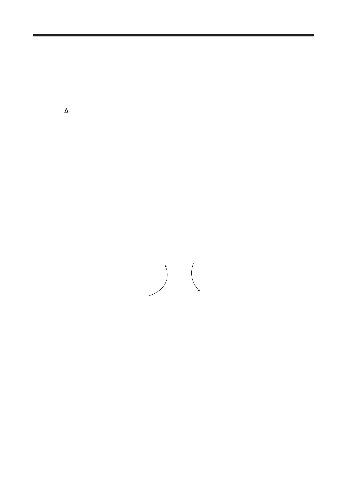
(Outside the cabinet) (Inside the cabinet)
Air flow
Fig. 10.2 Temperature distribution in an enclosed type cabinet
When air flows along the outer wall of the cabinet, effective heat exchange will be possible, because the
temperature slope inside and outside the cabinet will be steeper.
10. CHARACTERISTICS
10 - 8
10.3 Dynamic brake characteristics
CAUTION
The coasting distance is a theoretically calculated value that does not consider
factors such as friction. The calculated value will be longer than the actual
distance. If the braking distance is not longer than the calculated value, a moving
part may crash into the stroke end, causing a dangerous situation. Install an anti-
crash mechanism such as an air brake or an electric/mechanical stopper such as
a shock absorber to reduce the shock of moving parts.
POINT
Do not use dynamic brake to stop in a normal operation as it is the function to
stop in emergency.
For a machine operating at the recommended load to motor inertia ratio or less,
the estimated number of usage times of the dynamic brake is 1000 times while
the machine decelerates from the rated speed to a stop once in 10 minutes.
Be sure to enable EM1 (Forced stop 1) after servo motor stops when using EM1
(Forced stop 1) frequently in other than emergency.
Servo motors for MR-J4 may have the different coasting distance from that of
the previous model.
The electronic dynamic brake operates in the initial state for the HG series servo
motors of 600 W or smaller capacity. The time constant "τ" for the electronic
dynamic brake will be shorter than that of normal dynamic brake. Therefore,
coasting distance will be shorter than that of normal dynamic brake. For how to
set the electronic dynamic brake, refer to [Pr. PF06] and [Pr. PF12].