sh030106u.pdf - 第551页
16. FULLY CLOSE D L OOP SYS TEM 16 - 26 Symbol Name Explanation Unit f) Motor side c umu. feedback pulses (bef ore gear) Feedback puls es from the serv o motor encoder are counted and di splaye d. (Se rvo motor encoder u…
16. FULLY CLOSED LOOP SYSTEM
16 - 25
16.3.9 About MR Configurator2
Using MR Configurator2 can confirm if the parameter setting is normal or if the servo motor and the load-side
encoder operate properly.
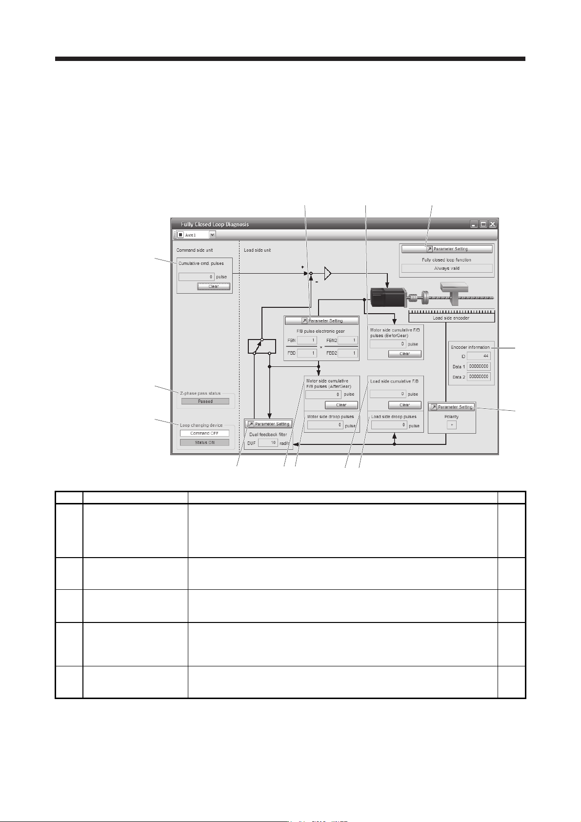
This section explains the fully closed diagnosis screen.
Click "Monitor start" to constantly read the monitor display items from the servo amplifier.
Then, click "Monitor stop" to stop reading. Click "Parameter read" to read the parameter items from the servo
amplifier, and then click "Parameter write" to write them.
f)
a)
c)
k)
b)
i)
h)
g)
d) e)
j)
m)
l)
Symbol Name Explanation Unit
a)
Motor side cumu. feedback
pulses (after gear)
Feedback pulses from the servo motor encoder are counted and displayed. (load-side
encoder unit)
When the set value exceeds 999999999, it starts with 0.
Click "Clear" to reset the value to 0.
The "-" symbol is indicated for reverse.
pulse
b) Motor side droop pulses
Droop pulses of the deviation counter between a servo motor-side position and a
command are displayed.
The "-" symbol is indicated for reverse.
pulse
c) Cumu. Com. pulses Position command input pulses are counted and displayed.
Click "Clear" to reset the value to 0.
The "-" symbol is indicated for reverse command.
pulse
d)
Load side cumu. feedback
pulses
Feedback pulses from the load-side encoder are counted and displayed.
When the set value exceeds 999999999, it starts with 0.
Click "Clear" to reset the value to 0.
The "-" symbol is indicated for reverse.
pulse
e) Load side droop pulses
Droop pulses of the deviation counter between a load-side position and a command are
displayed.
The "-" symbol is indicated for reverse.
pulse
16. FULLY CLOSED LOOP SYSTEM
16 - 26
Symbol Name Explanation Unit
f)
Motor side cumu. feedback
pulses (before gear)
Feedback pulses from the servo motor encoder are counted and displayed. (Servo
motor encoder unit)
When the set value exceeds 999999999, it starts with 0.
Click "Clear" to reset the value to 0.
The "-" symbol is indicated for reverse.
pulse
g) Encoder information The load-side encoder information is displayed.
The display contents differ depending on the load-side encoder type.
ID: The ID No. of the load-side encoder is displayed.
Data 1: For the incremental type linear encoder, the counter from powering on is
displayed. For the absolute position type linear encoder, the absolute position
data is displayed.
Data 2: For the incremental type linear encoder, the distance (number of pulses) from
the reference mark (Z-phase) is displayed. For the absolute position type
linear encoder, "00000000" is displayed.
h) Polarity
For address increasing direction in the servo motor CCW, it is indicated as "+" and for
address decreasing direction in the servo motor CCW, as "-".
i) Z phase pass status
If the fully closed loop system is "Disabled", the Z-phase pass status of the servo motor
encoder is displayed. If the fully closed loop system is "Enabled" or "Semi closed loop
control/fully closed loop control switching", the Z-phase pass status of the load-side
encoder is displayed.
j)
Fully closed loop changing
device
Only if the fully closed loop system is "Semi closed loop control/fully closed loop control
switching", the device is displayed.
The state of the semi closed loop control/fully closed loop control switching signal and
the inside state during selection are displayed.
k)
Parameter (Feedback pulse
electronic gear)
The feedback pulse electronic gears ([Pr. PE04], [Pr. PE05], [Pr. PE34], and [Pr. PE35])
are displayed/set for servo motor encoder pulses in this parameter. (Refer to section
16.3.1 (5).)
l)
Parameter (Dual feedback
filter)
The band of [Pr. PE08 Fully closed loop dual feedback filter] is displayed/set in this
parameter.
m)
Parameter (fully closed loop
selection)
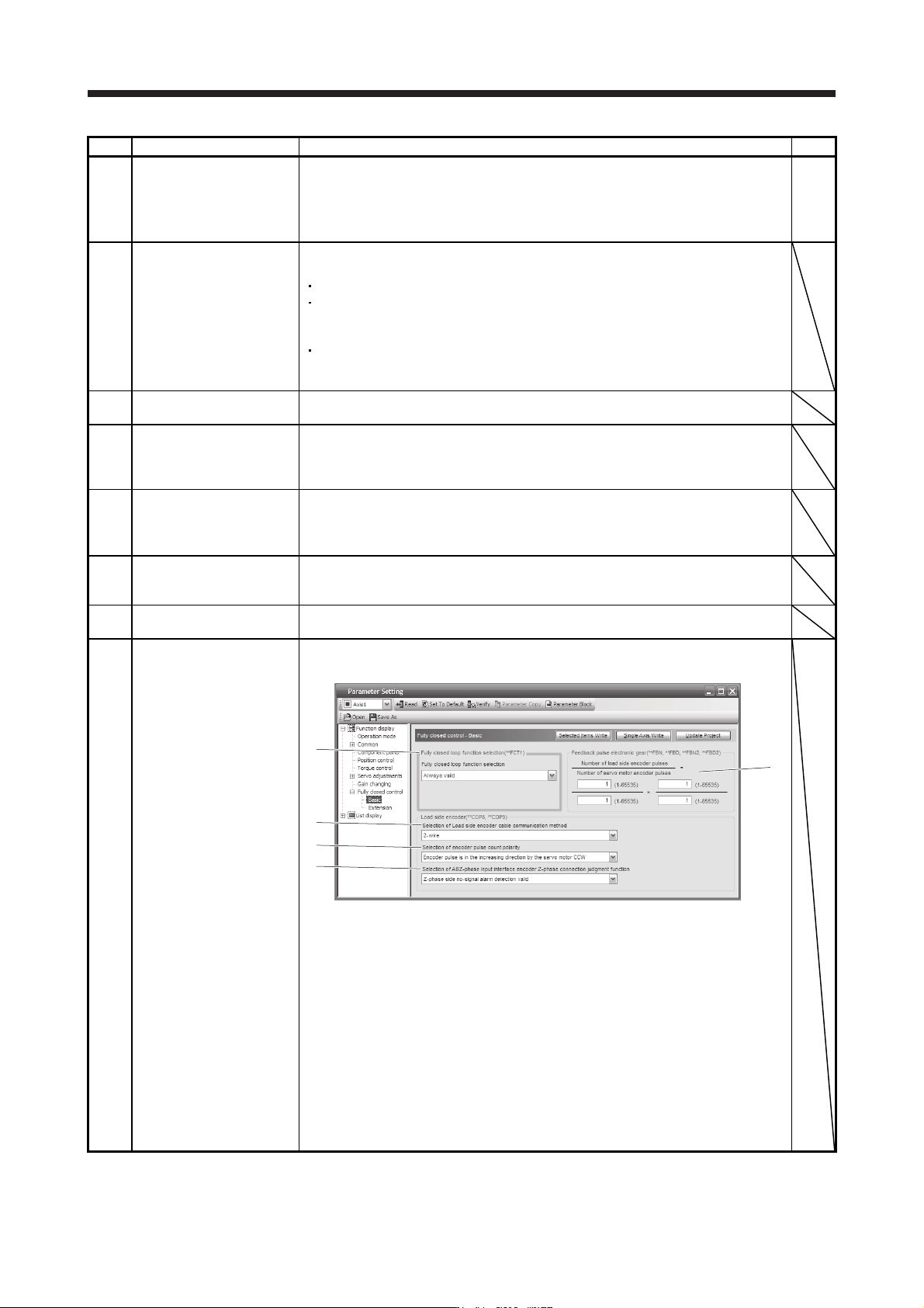
The parameter for the fully closed loop control is displayed or set.
Click "Parameter setting" to display the "Fully closed loop control - Basic" window.
1)
2)
3)
4)
5)
1) Fully closed loop selection ([Pr. PE01])
"Always valid" or "Switching with the control command of controller" is selected here.
2) Feedback pulse electronic gear ([Pr. PE04], [Pr. PE05], [Pr. PE34], [Pr. PE35])
Setting of feedback pulse electronic gear
3) Load-side encoder cable communication method selection ([Pr. PC26])
4) Selection of encoder pulse count polarity ([Pr. PC27])
Polarity of the load-side encoder information is selected.
5) Selection of A/B/Z-phase input interface encoder Z-phase connection judgment
function ([Pr. PC27])
Select the non-signal detection status for the pulse train signal from the A/B/Z-phase
input interface encoder used as a linear encoder or load-side encoder.
17. APPLICATION OF FUNCTIONS
17 - 1
17. APPLICATION OF FUNCTIONS
This chapter explains application of using servo amplifier functions.
17.1 J3 compatibility mode
POINT
The fully closed loop control in the J3 compatibility mode is available for the
servo amplifiers with software version A3 or later.
Specifications of the J3 compatibility mode of the servo amplifier with software
version A4 or earlier differ from those with software version A5 or later.
The J3 compatibility mode is not compatible with the master-slave operation
function.
17.1.1 Outline of J3 compatibility mode
MR-J4W_-_B servo amplifiers and MR-J4-_B_(-RJ) servo amplifiers have two operation modes: "J4 mode" is
for using all functions with full performance and "J3 compatibility mode" for using the conventional MR-J3-B
servo amplifiers.
When you connect a servo amplifier with SSCNET III/H communication for the first controller communication
by factory setting, the operation mode will be fixed to "J4 mode". To restore the factory settings or select a
desired mode, change the settings using the application "MR-J4(W)-B mode selection" or "MR Mode
Change".
The application "MR-J4(W)-B mode selection" or "MR Mode Change" is included in MR Configurator2 with
version 1.12N or later. The application "MR-J4(W)-B mode selection" is packed with MR Configurator2 of
software version 1.12N or later.
For information on the operating conditions of the application "MR-J4(W)-B mode selection" and "MR Mode
Change", refer to the operating conditions of MR Configurator2. (Refer to section 11.7.)
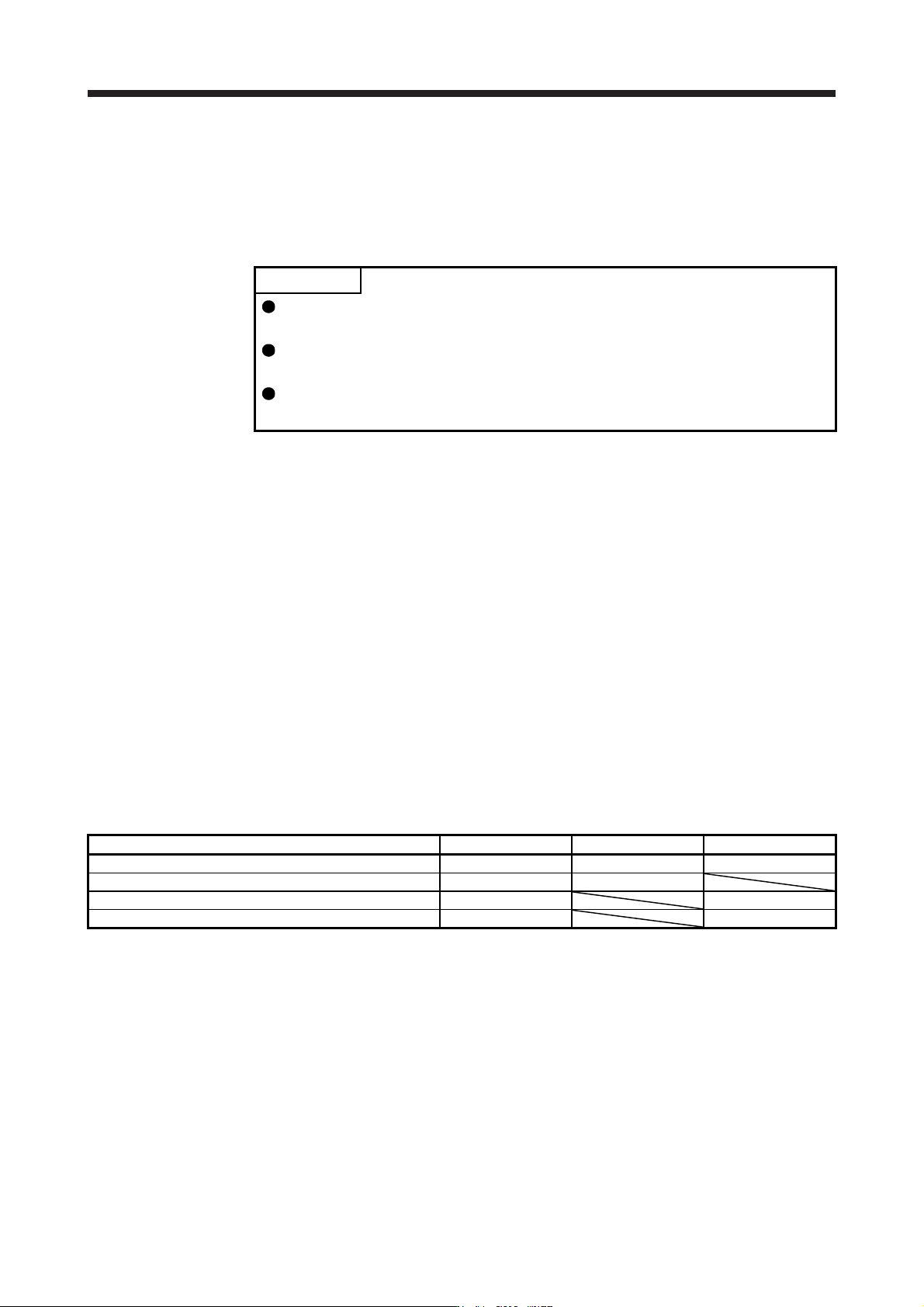
17.1.2 Operation modes supported by J3 compatibility mode
The J3 compatibility mode supports the following operation modes.
Operation mode in J3 compatibility mode Model of MR-J3-_B Model of MR-J3-_BS Model of MR-J3W-_B
MR-J3-B standard control mode (rotary servo motor) MR-J3-_B MR-J3-_BS MR-J3W-_B
MR-J3-B fully closed loop control mode MR-J3-_B-RJ006 MR-J3-_BS
MR-J3-B linear servo motor control mode MR-J3-_B-RJ004 MR-J3W-_B
MR-J3-B DD motor control mode MR-J3-_B-RJ080W MR-J3W-_B
Each operation mode has the same ordering as conventional MR-J3-B series servo amplifiers and is
compatible with their settings.
In addition, the control response characteristic in the J3 compatibility mode will be the same as that of MR-J3
series. By enabling the J3 extension function, control response will be equal to MR-J4 series using a
controller compatible with SSCNET III.