sh030106u.pdf - 第72页
2. INSTALLATION 2 - 3 (b) Ins tallation of two or more servo amp lifiers POINT Close mou nting is possib le depe nding on the ca pacity of the s er vo am plifier. Refer to sec tion 1.3 for availab ility of c lose moun ti…
2. INSTALLATION
2 - 2
2.1 Installation direction and clearances
CAUTION
The equipment must be installed in the specified direction. Otherwise, it may
cause a malfunction.
Leave specified clearances between the servo amplifier and the cabinet walls or
other equipment. Otherwise, it may cause a malfunction.
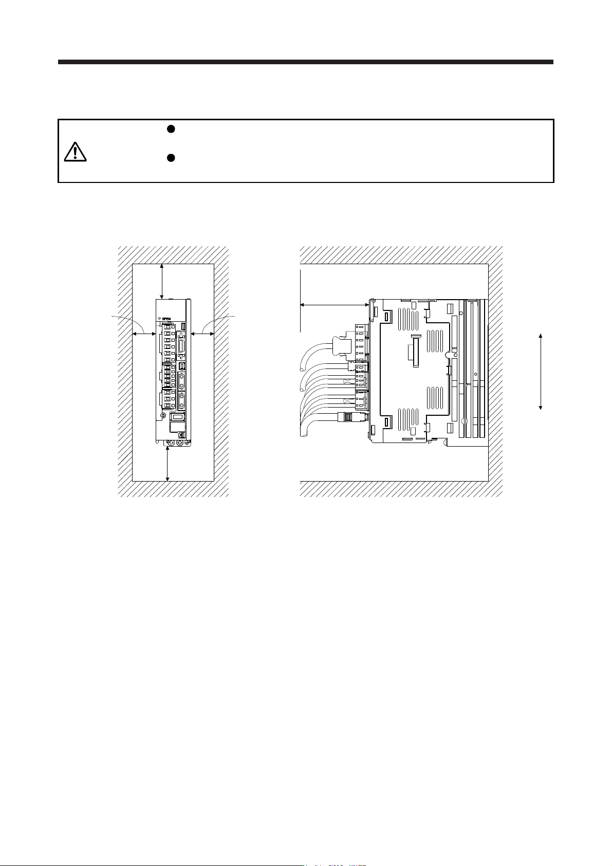
(1) Installation clearances of the servo amplifier
(a) Installation of one servo amplifier
40 mm or more
10 mm
or more
10 mm
or more
(Note 2)
40 mm
or more
(Note 1)
Servo amplifier
Cabinet Cabinet
Wiring allowance
80 mm or more
Top
Bottom
Note 1. For 11 kW to 22 kW servo amplifiers, the clearance between the bottom and
g
round will be 120 mm or more.
2. When mountin
g
MR-J4-500B
(
-RJ
)
, maintain a minimum clearance of 25 mm on the left side.
2. INSTALLATION
2 - 3
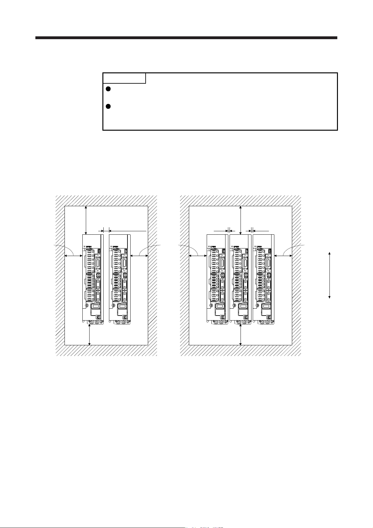
(b) Installation of two or more servo amplifiers
POINT
Close mounting is possible depending on the capacity of the servo amplifier.
Refer to section 1.3 for availability of close mounting.
When closely mounting multiple servo amplifiers, the servo amplifier on the right
must have a larger depth than that on the left. Otherwise, the CNP1, CNP2, and
CNP3 connectors cannot be removed.
Leave a large clearance between the top of the servo amplifier and the cabinet walls, and install a
cooling fan to prevent the internal temperature of the cabinet from exceeding the environment.
When mounting the servo amplifiers closely, leave a clearance of 1 mm between the adjacent servo
amplifiers in consideration of mounting tolerances. In this case, keep the ambient temperature within
0 ˚C to 45 ˚C or use the servo amplifier with 75% or less of the effective load ratio.
100 mm or more
10 mm or more
(Note 2)
30 mm
or more
30 mm
or more
40 mm or more
(Note 1)
Cabinet
Top
Bottom
100 mm or more
1 mm
30 mm
or more
40 mm or more
Cabinet
1 mm
Leaving clearance Mounting closely
Note 1. For 11 kW to 22 kW servo amplifiers, the clearance between the bottom and
g
round will be 120 mm or more.
2. When mounting MR-J4-500B(-RJ), maintain a minimum clearance of 25 mm between the MR-J4-500B(-RJ) and a servo
amplifier mounted on the left side.
(2) Others
When using heat generating equipment such as the regenerative option, install them with full
consideration of heat generation so that the servo amplifier is not affected.
Install the servo amplifier on a perpendicular wall in the correct vertical direction.
2. INSTALLATION
2 - 4
2.2 Keeping out of foreign materials
(1) When drilling in the cabinet, prevent drill chips and wire fragments from entering the servo amplifier.
(2) Prevent oil, water, metallic dust, etc. from entering the servo amplifier through openings in the cabinet or
a cooling fan installed on the ceiling.
(3) When installing the cabinet in a place where toxic gas, dirt and dust exist, conduct an air purge (force
clean air into the cabinet from outside to make the internal pressure higher than the external pressure) to
prevent such materials from entering the cabinet.
2.3 Encoder cable stress
(1) The way of clamping the cable must be fully examined so that bending stress and cable's own weight
stress are not applied to the cable connection.
(2) For use in any application where the servo motor moves, fix the cables (encoder, power supply, and
brake) with having some slack from the connector connection part of the servo motor to avoid putting
stress on the connector connection part. Use the optional encoder cable within the bending life range.
Use the power supply and brake wiring cables within the bending life of the cables.
(3) Avoid any probability that the cable insulator might be cut by sharp chips, rubbed by a machine corner or
stamped by workers or vehicles.
(4) For installation on a machine where the servo motor moves, the bending radius should be made as large
as possible. Refer to section 10.4 for the bending life.
2.4 SSCNET III cable laying
SSCNET III cable is made from optical fiber. If optical fiber is added a power such as a major shock, lateral
pressure, haul, sudden bending or twist, its inside distorts or breaks, and optical transmission will not be
available. Especially, as optical fiber for MR-J3BUS_M/MR-J3BUS_M-A is made of synthetic resin, it melts
down if being left near the fire or high temperature. Therefore, do not make it touched the part, which can
become hot, such as heat sink or regenerative option of servo amplifier.
Read described item in this section carefully and handle it with caution.
(1) Minimum bend radius
Make sure to lay the cable with greater radius than the minimum bend radius. Do not press the cable to
edges of equipment or others. For SSCNET III cable, the appropriate length should be selected with due
consideration for the dimensions and arrangement of servo amplifier. When closing the door of cabinet,
pay careful attention for avoiding the case that SSCNET III cable is hold down by the door and the cable
bend becomes smaller than the minimum bend radius. For the minimum bend radius, refer to section
11.1.3.