sh030106u.pdf - 第656页
APPENDIX App. - 25 2) 3) 4) 1 ) App. 8 Two-w ire type encod er cable for HG-MR /HG-KR Use a two- wire typ e encod er cable for the f ully c losed loo p con trol by the MR-J4-_B_ s ervo amplifiers . For MR-E KCBL_M-_ enc …

APPENDIX
App. - 24
App. 7 How to replace servo amplifier without magnetic pole detection
CAUTION
Be sure to write the magnetic pole information of the servo amplifier before the
replacement to the servo amplifier after the replacement. If the information before
and after replacement are different, the servo motor may operate unexpectedly.
When replacing the servo amplifier, carry out the magnetic pole detection again. If the magnetic pole
detection cannot be performed unavoidably, write the magnetic pole information from the servo amplifier
before the replacement to the one after the replacement using MR Configurator2.
(1) Procedures
(a) Read the magnetic pole information of the servo amplifier before the replacement.
(b) Write the read magnetic pole information to the servo amplifier after the replacement.
(c) Perform the test operation with the torque limit for ensuring the safety, and confirm that there is no
trouble.
(2) Migration method of the magnetic pole information
(a) How to read the magnetic pole information from the servo amplifier before the replacement
1) Open the project in MR Configurator2, select "MR-J4-B" for model, and select "Linear" for
operation mode.
2) Check that the personal computer is connected with the servo amplifier, and select "Diagnosis"
and then "Linear diagnosis".
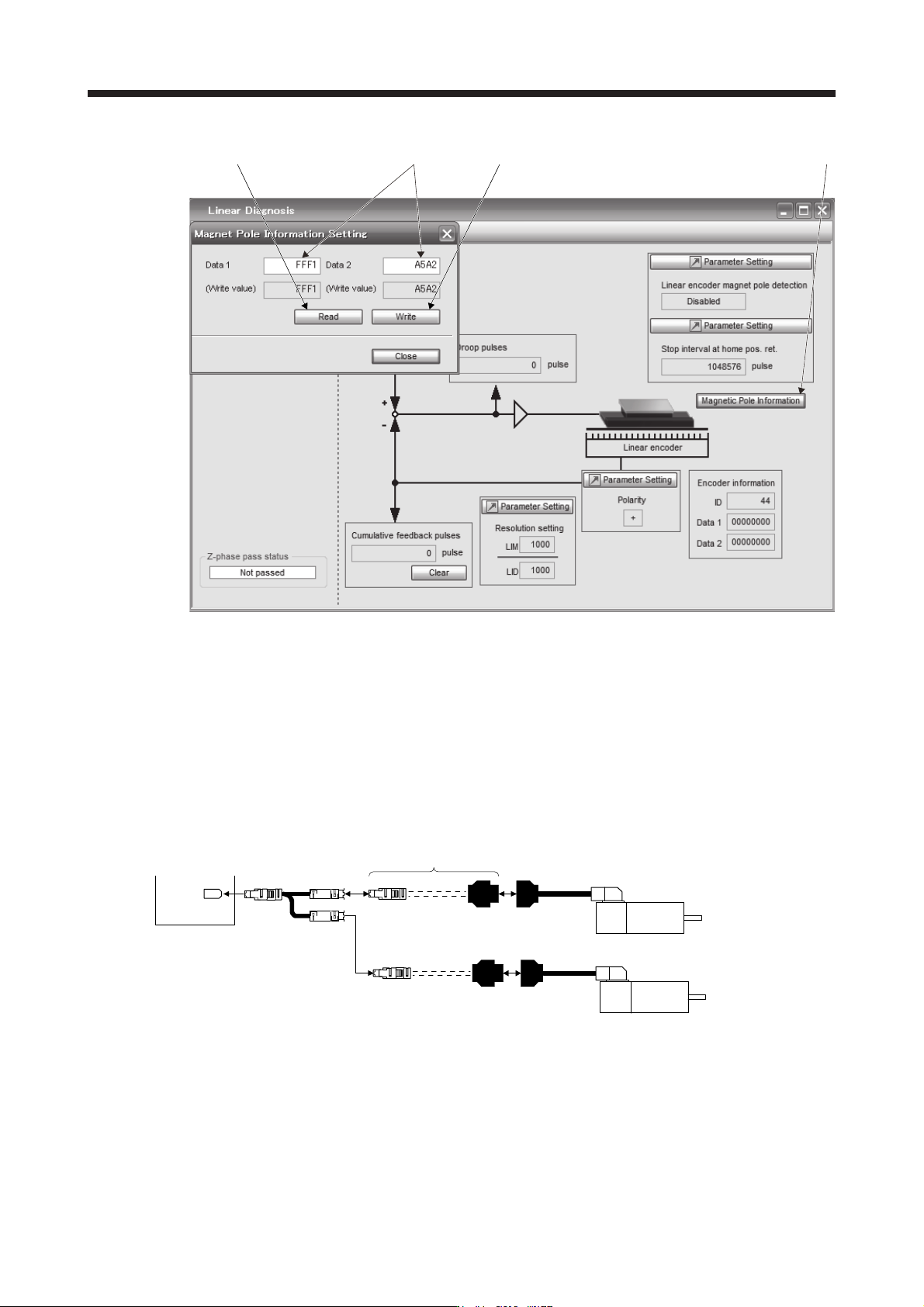
3) Click "Magnetic pole information" ( 1) in figure) to open the magnetic pole information window.
4) Click "Read All" of the magnetic pole information window. ( 2) in figure)
5) Confirm the data 1 and data 2 ( 3) in figure) of the magnetic pole information window and take
notes.
(b) How to write the magnetic pole information to the servo amplifier after the replacement
1) Open the project in MR Configurator2, select "MR-J4-B" for model, and select "Linear" for
operation mode.
2) Check that the personal computer is connected with the servo amplifier, and select "Diagnosis"
and then "Linear diagnosis".
3) Click "Magnetic pole information" ( 1) in figure) to open the magnetic pole information window.
4) Input the value of the magnetic pole information taken notes to the data 1 and data 2 ( 3) in
figure) of the magnetic pole information window.
5) Click "Write All" ( 4) in figure) of the magnetic pole information window.
6) Cycle the power of the servo amplifier.
APPENDIX
App. - 25
2) 3) 4) 1)
App. 8 Two-wire type encoder cable for HG-MR/HG-KR
Use a two-wire type encoder cable for the fully closed loop control by the MR-J4-_B_ servo amplifiers.
For MR-EKCBL_M-_ encoder cables for HG-MR and HG-KR, up to 20 m cables are two-wire type. If a two-
wire type encoder cable with a length of 20 m or more is required, fabricate it using the MR-ECNM connector
set as shown in the internal wiring diagram of this section. In this case, the cable should not be longer than
50 m.
App. 8.1 Configuration diagram
Servo amplifier
CN2
Fabricate a two-wire type
encoder cable.
CN2 MOTOR
SCALE
Servo motor
HG-KR
HG-MR
Servo motor
HG-KR
HG-MR
For driving
For load-side encode
r
APPENDIX
App. - 26
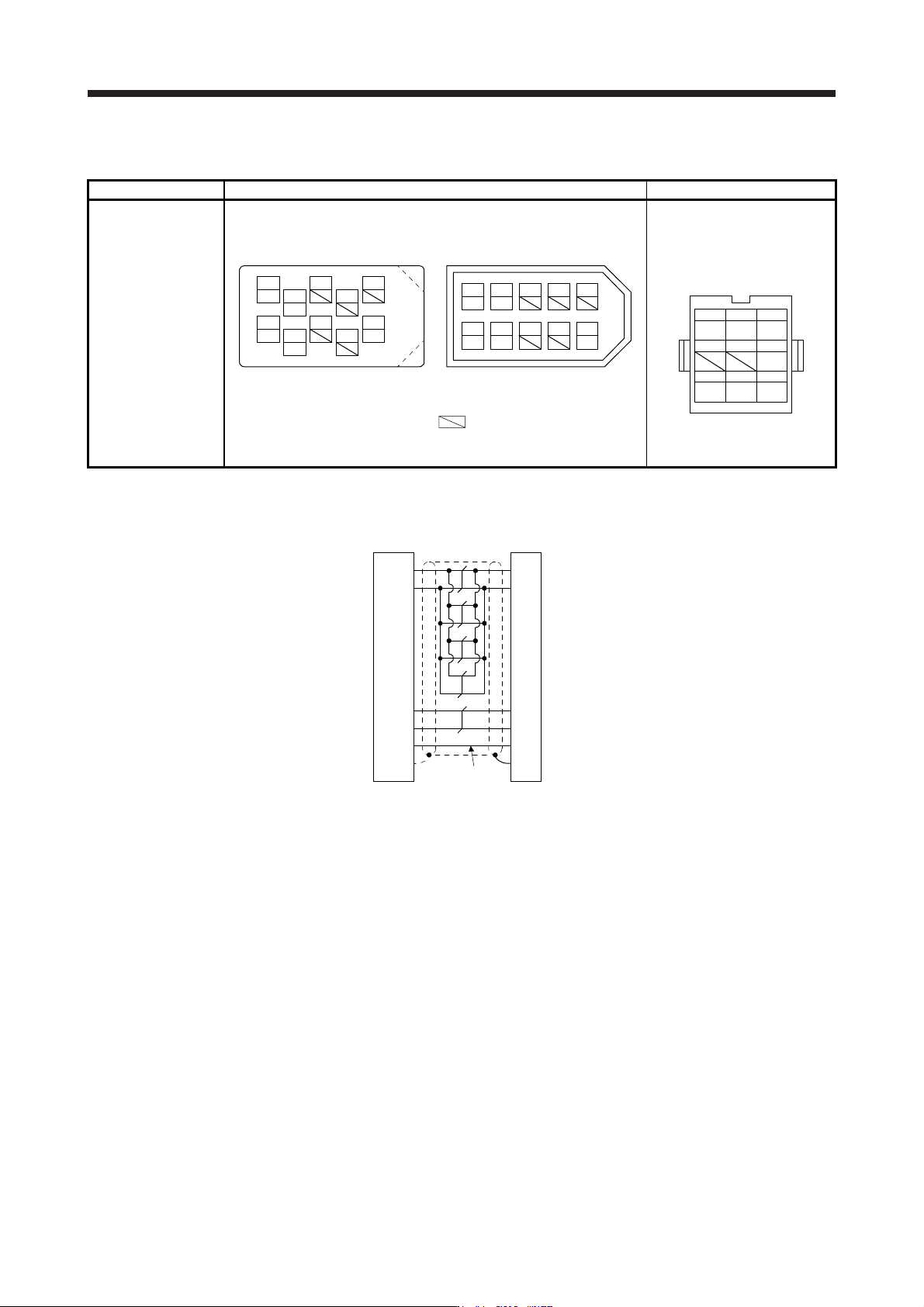
App. 8.2 Connector set
Connector set 1) Servo amplifier-side connector 2) Servo motor-side connector
MR-ECNM Receptacle: 36210-0100PL
Shell kit: 36310-3200-008
(3M)
Connector set: 54599-1019
(Molex)
Housing: 1-172161-9
Connector pin: 170359-1
(TE Connectivity or equivalent)
Cable clamp: MTI-0002
(Toa Electric Industrial)
MR
123
MRR BAT
456
P5
789
LG SHD
View seen from wiring side.
CONT
MRR
LG
P5
MR
BAT
4
2
8
6
15
10
37
9
View seen from wiring side. (Note)
or
P5 MR
BAT
MRR
LG
13 79
428610
5
V
iew seen from wiring side. (Note
)
Note. Keep open the pins shown with . Especially, pin 10 is provided
for manufacturer adjustment. If it is connected with any other pin, the
servo amplifier cannot operate normall
y
.
App. 8.3 Internal wiring diagram
(Note)
P5
LG
1
2
MR
MRR
3
4
3
7
9
SD
Plate
1
2
8
9
LG
MR
MRR
SHD
P5
BATBAT
Servo amplifier-side
connector
Servo motor-side
connector
Note.
A
lways make connection for use in an absolute position detection system. Wiring is
not necessar
y
for use in an incremental s
y
stem.