sh030106u.pdf - 第508页
15. USIN G A DI REC T DRIV E MOTOR 15 - 5 15.3.1 Star tup proc edure Sta rt up th e dire ct drive servo system i n the followi ng proce du re. Absolute position detection system Installation and wiring Z-phase pulse of t…
15. USING A DIRECT DRIVE MOTOR
15 - 4
CAUTION
When using the regenerative resistor, switch power off with the alarm signal.
Otherwise, a transistor fault or the like may overheat the regenerative resistor,
causing a fire.
Do not modify the equipment.
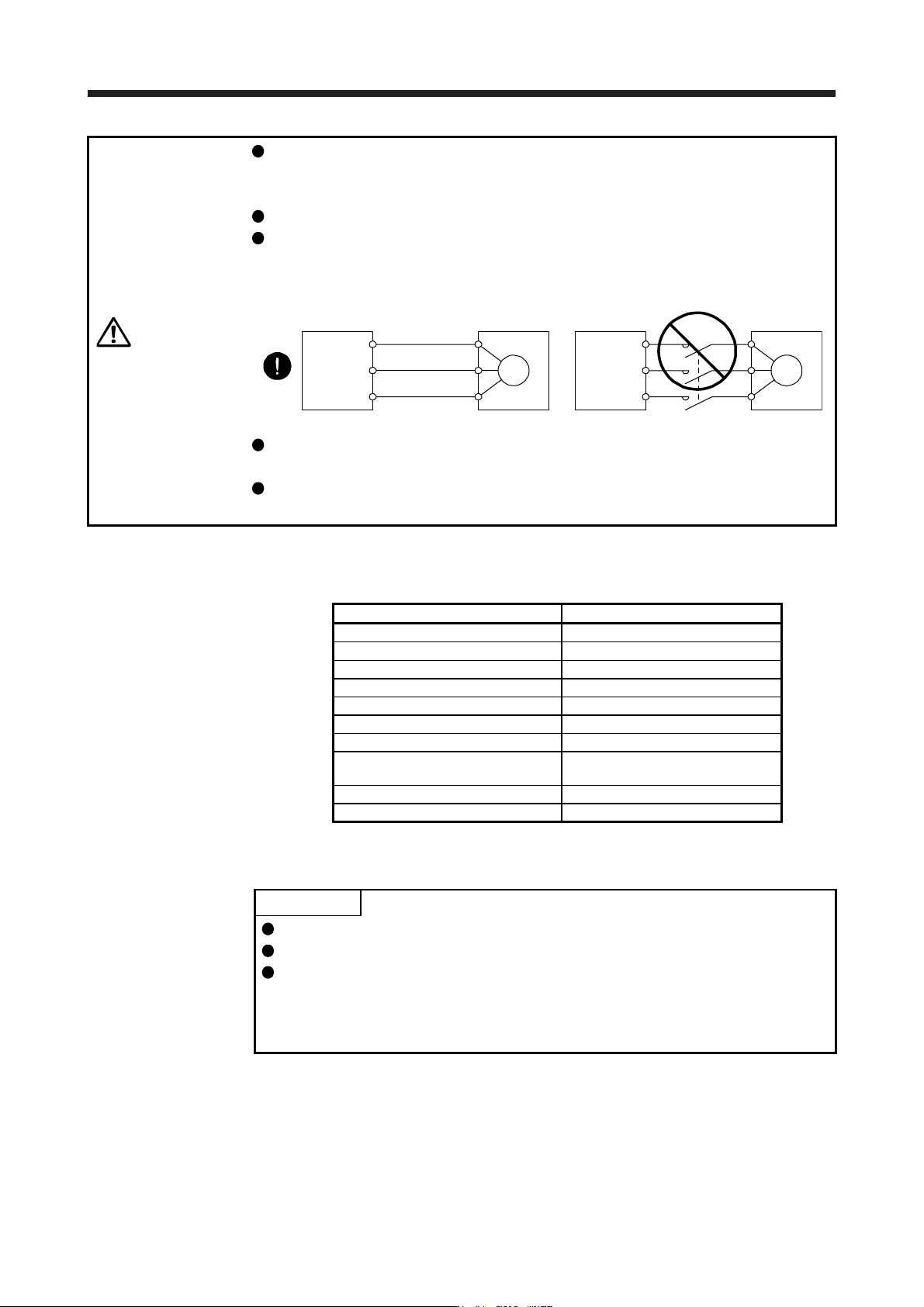
Connect the servo amplifier power output (U/V/W) to the power input of the direct
drive motor (U/V/W) directly. Do not let a magnetic contactor, etc. intervene.
Otherwise, it may cause a malfunction.
Servo amplifier Servo amplifier
Direct drive
motor
Direct drive
motor
U
M
V
W
U
V
W
U
M
V
W
U
V
W
Connecting a servo motor for different axis to the U, V, W, or CN2 may cause a
malfunction.
Before wiring, switch operation, etc., eliminate static electricity. Otherwise, it may
cause a malfunction.
This chapter does not describe the following items. For details of the items, refer to each section of the
detailed description field.
Item Detailed explanation
Input power supply circuit Section 3.1
Explanation of power supply system Section 3.3
Signal (device) explanations Section 3.5
Alarm occurrence timing chart Section 3.7
Interfaces Section 3.8
SSCNET III cable connection Section 3.9
Grounding Section 3.11
Switch setting and display of the servo
amplifier
Section 4.3
PARAMETERS Chapter 5
TROUBLESHOOTING Chapter 8
15.3 Operation and functions
POINT
When using the direct drive motor, set [Pr. PA01] to "_ _ 6 _".
For the test operation, refer to section 4.4.
The Z-phase pulse of the direct drive motor must be turned on after power-on.
When the machine configuration does not allow one or more revolution of the
direct drive motor, install the direct drive motor so that the Z-phase pulse can be
turned on.
15. USING A DIRECT DRIVE MOTOR
15 - 5
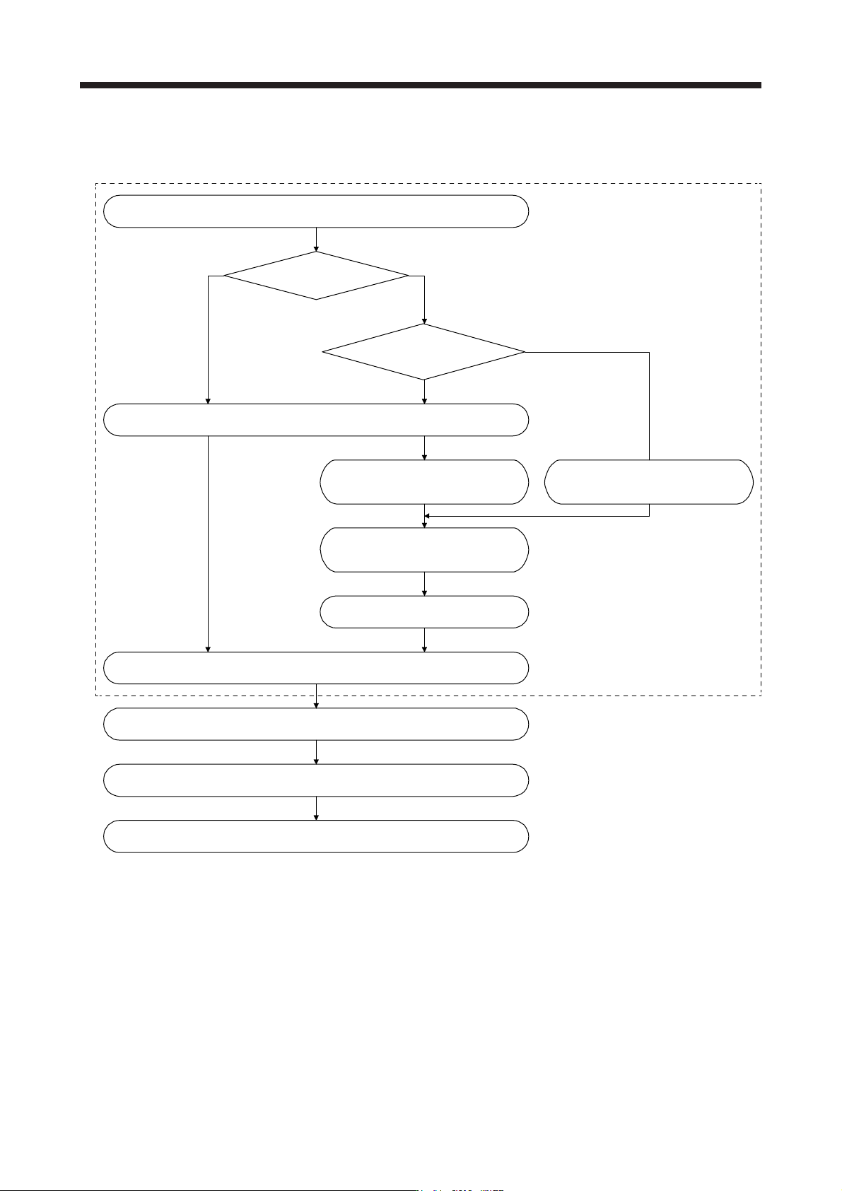
15.3.1 Startup procedure
Start up the direct drive servo system in the following procedure.
Absolute position detection system
Installation and wiring
Z-phase pulse of the direct drive motor
is turned on by the JOG operation.
(Notes 1 and 2)
Perform the magnetic pole detection. (Refer to section 15.3.2.) (Note 1)
Absolute position
detection system?
Incremental system
Can you manually turn
on the Z-phase pulse of the
direct drive motor?
Change the setting to disable the
magnetic pole detection.
(Refer to section 15.3.2.)
Z-phase pulse of the direct drive motor
is turned on manually. (Note 3)
Turn the servo amplifier power
off and on again. (Note 2)
Positioning operation check using the test operation mode (Note 1)
Positioning operation check using the controller (Refer to section 15.3.3.)
Home position return operation (Refer to the manual of the controller.)
Positioning operation
No
Yes
Perform this procedure once at startup.
Note 1. Use MR Confi
g
urator2.
2. For the absolute position detection system, always turn on the Z-phase pulse of the direct drive motor while the servo amplifier
power is on, and then turn the servo amplifier power supply off and on again. By turning off and on the power supply, the
absolute position becomes confirmed. Without this operation, the absolute position will not be regained properly, and a
warnin
g
will occur at the controller.
3. If the Z-phase pulse of the direct drive motor can be turned on manually, the Z-phase pulse does not have to be turned on by
the magnetic pole detection or the JOG operation.
For this operation, make sure to connect the direct drive motor encoder and the servo amplifier, and turn on the control circuit
power suppl
y
of the servo amplifier
(
L11/L21
)
(
turn off the main circuit power suppl
y
L1, L2, and L3
)
. Ensure safet
y
at this time.

15. USING A DIRECT DRIVE MOTOR
15 - 6
15.3.2 Magnetic pole detection
POINT
The magnetic pole detection is not required for the configured absolute position
detection system where the Z-phase pulse of the direct drive motor can be
turned on manually.
For this operation, always connect the direct drive motor encoder and the servo
amplifier and turn on the control circuit power supply of the servo amplifier.
Perform this operation by considering the safety.
When performing a magnetic pole detection without using FLS (Upper stroke
limit) and RLS (Lower stroke limit), set [Pr. PL08 Linear servo motor/DD motor
function selection 3] to "_ 1 _ _" to disable FLS and RLS.
Set [Pr. PE47 Torque offset] to "0 (initial value)" before executing the magnetic
pole detection.
For the magnetic pole detection of vertical axis with direct drive motors, refer to
section 2.1 of "Direct Drive Motor Instruction Manual".
Before the positioning operation of the direct drive motor, make sure to perform the magnetic pole detection.
Before starting up the equipment, perform the test operation (positioning operation) of MR Configurator2.