sh030106u.pdf - 第432页
11. OPT I ONS AND PER IPH ERA L EQU IPM ENT 11 - 11 1 (4) Dim ensions (a) DBU-11 K/DBU-15K/D BU-22K-R1 [Unit: mm] C D 100 D 5 E E B A 5 F 2.3 G ab 1 3 Terminal block 14 Screw: M3.5 Tightening t orque: 0. 8 [N•m] UV W Scr…
11. OPTIONS AND PERIPHERAL EQUIPMENT
11 - 110
(b) Whe
n the forced stop deceleration function is not used
1) Ready-off command from controller
For information on the ready-off command from controller, refer to section 11.17 (3)
(a) 1).
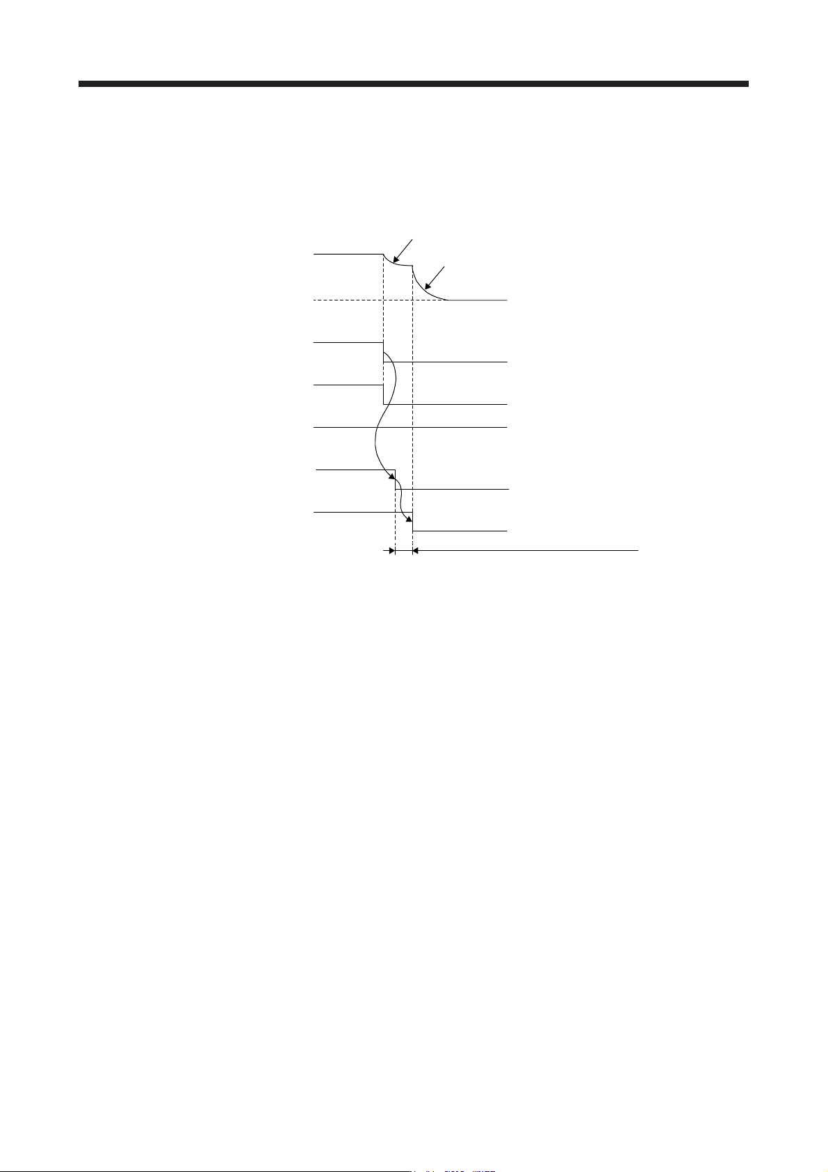
2) Turning the forced stop command (from controller) or EM1 (Forced stop 1) off
ON
OFF
0 r/min
ON
OFF
Coasting
Dynamic brake
Servo motor speed
Release
Activate
DB (Dynamic
brake interlock) (Note 1)
Dynamic brake
Emergency stop command
(from controller) or EM1
(Forced stop 1)
Base circuit
(Energy supply to
the servo motor)
Disabled (ON)
Enabled (OFF)
ON (no alarm)
OFF (alarm)
ALM
(Malfunction)
Release delay time and external relay, etc. (Note 2)
Note 1. ON: Dynamic brake is not activated
OFF: D
y
namic brake is activated
2. There is delay caused by the magnetic contactor built into the external dynamic brake (about 50 ms) and delay caused by the
external rela
y
.
3) Alarm oc
currence
For information on the alarm occurrence, refer to section 11.17 (3) (a) 3) b).
4)
When both the main circuit power supply and the control circuit power supply are turned off
For information on when both the main circuit power supply and the control circuit power supply
are turned off, refer to section 11.17 (3) (a) 4).
11. OPTIONS AND PERIPHERAL EQUIPMENT
11 - 111
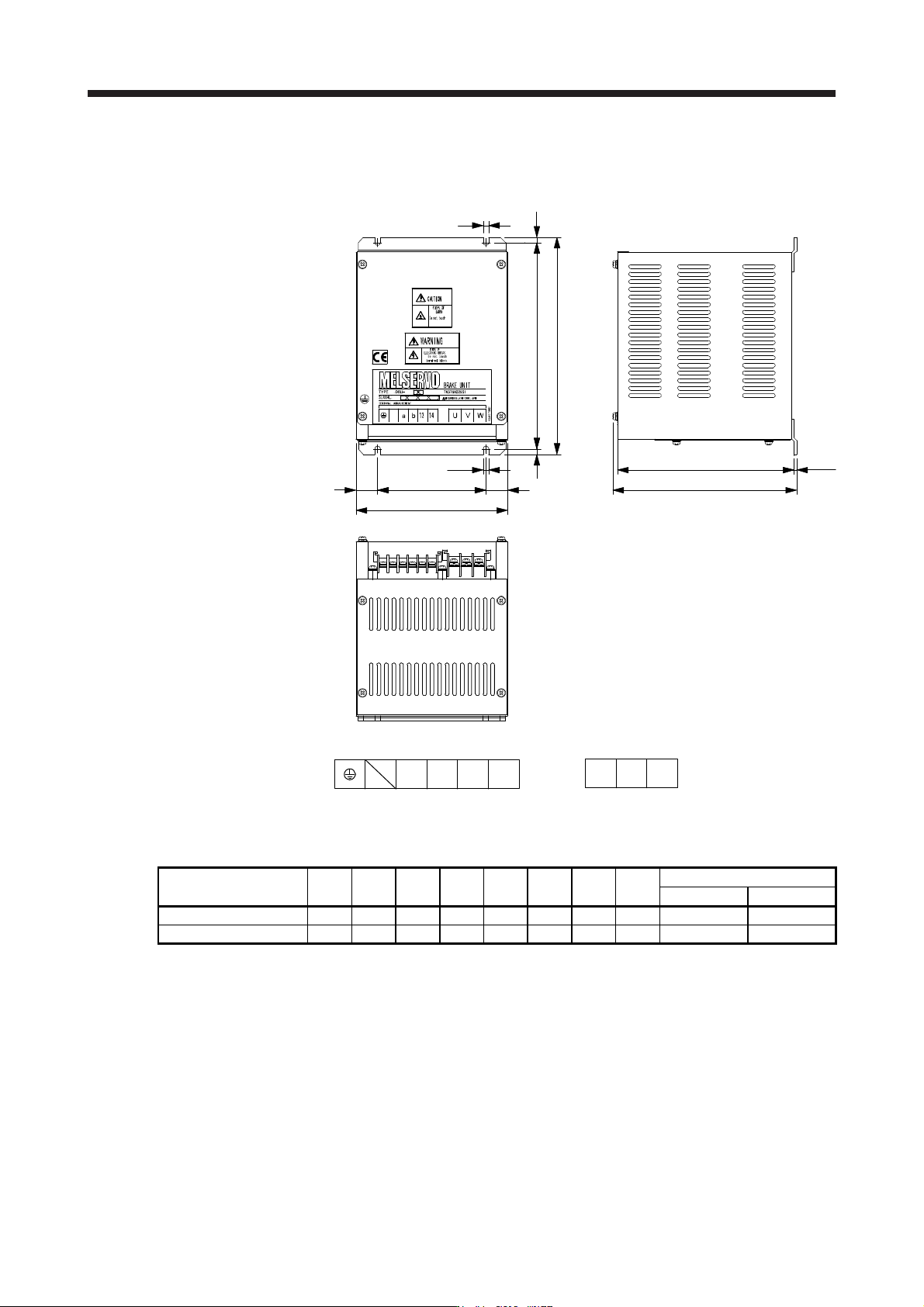
(4) Dim
ensions
(a) DBU-11K/DBU-15K/DBU-22K-R1
[Unit: mm]
C
D 100 D
5
E EB
A
5
F
2.3G
ab13
Terminal block
14
Screw: M3.5
Tightening torque: 0.8 [N•m]
UVW
Screw: M4
Tighteni
ng torque: 1.2 [N•m]
External dynamic brake A B C D E F G
Mass
[kg
]
(Note) Connection wire [mm
2
]
U/V/W Except U/V/W
DBU-11K 200 190 140 20 5 170 163.5 2 5.5 (AWG 10) 2 (AWG 14)
DBU-15K/DBU-22K-R1 250 238 150 25 6 235 228 6 5.5 (AWG 10) 2 (AWG 14)
Note. Selection conditions of wire size are as follows.
600 V grade heat-resistant polyvinyl chloride insulated wire (HIV wire)
Construction condition: Sin
g
le wire set in midai
r
11. OPTIONS AND PERIPHERAL EQUIPMENT
11 - 112
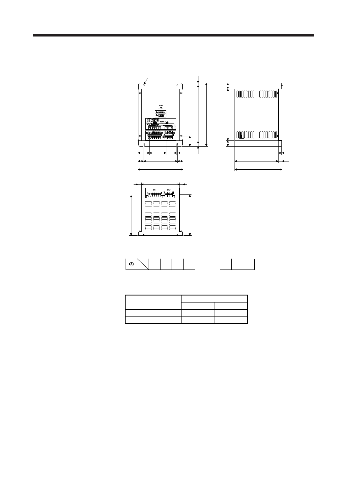
(b) DBU-11K-4/D
BU-22K-4
[Unit: mm]
15
51
25
15
73.75 7
25150
10
200
170
178.5
179.5
15
260
280
43
10
2-φ7 mounting hole
195
228
2626
210
2.3
Mass: 6.7 [kg]
Terminal block
TE1
a b 13 14
Screw: M3.5
Tightening torque: 0.8 [N•m]
TE2
WVU
Screw: M4
Tightening torque: 1.2 [N•m]
External dynamic brake
(Note) C
onnection wire [mm
2
]
U/V/W Except U/V/W
DBU-11K-4 5.5 (AWG 10) 2 (AWG 14)
DBU-22K-4 5.5 (AWG 10) 2 (AWG 14)
Note. Selection conditions of wire size are as follows.
Wire type: 600 V grade heat-resistant polyvinyl chloride insulated wire (HIV wire)
Construction condition: Sin
g
le wire set in midai
r