sh030106u.pdf - 第269页
8. TRO UBLESHO OTING 8 - 2 8.2 Alar m list No. Name Detail No. Detail name Stop meth od (Note 2, 3) Alarm de activati on Alarm reset CPU reset Cycling the power Alarm 10 Unde rvol tage 10.1 Voltage d rop in the cont rol …
8. TROUBLESHOOTING
8 - 1
8. TROUBLESHOOTING
POINT
Refer to "MELSERVO-J4 Servo Amplifier Instruction Manual (Troubleshooting)"
for details of alarms and warnings.
As soon as an alarm occurs, make the Servo-off status and interrupt the main
circuit power.
[AL. 37 Parameter error] and warnings (except [AL. F0 Tough drive warning]) are
not recorded in the alarm history.
When an error occurs during operation, the corresponding alarm and warning are displayed. When an alarm
or warning is displayed, refer to "MELSERVO-J4 Servo Amplifier Instruction Manual (Troubleshooting)" to
remove the failure. When an alarm occurs, ALM will turn off.
8.1 Explanation for the lists
(1) No./Name/Detail No./Detail name
Indicates each No./Name/Detail No./Detail name of alarms or warnings.
(2) Stop method
For the alarms and warnings in which "SD" is written in the stop method column, the servo motor stops
with the dynamic brake after forced stop deceleration. For the alarms and warnings in which "DB" or
"EDB" is written in the stop method column, the servo motor stops with the dynamic brake without forced
stop deceleration.
(3) Alarm deactivation
After the cause of the alarm has been removed, the alarm can be deactivated by any of the methods
marked
in the alarm deactivation column. Warnings are automatically canceled after the cause of
occurrence is removed. Alarms are deactivated with alarm reset, CPU reset, or cycling the power.
Alarm deactivation Explanation
Alarm reset 1. Reset command from controller
2. Clicking "Occurred Alarm Reset" in the "Alarm Display" window of MR
Configurator2
CPU reset Resetting the controller itself
Cycling the power Turning the power off and then turning it on again.
8. TROUBLESHOOTING
8 - 2
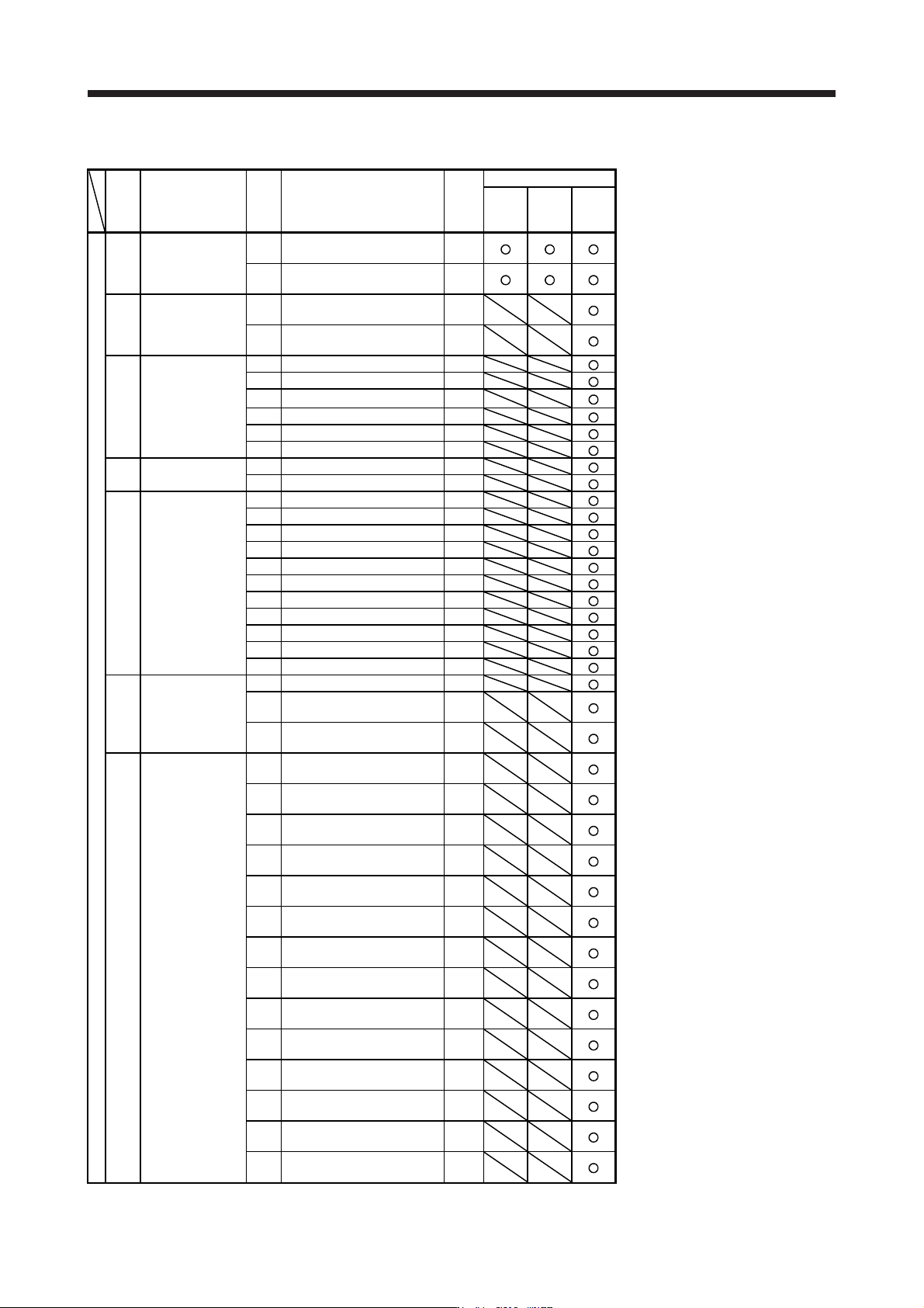
8.2 Alarm list
No. Name
Detail
No.
Detail name
Stop
method
(Note
2, 3)
Alarm deactivation
Alarm
reset
CPU
reset
Cycling
the
power
Alarm
10 Undervoltage
10.1
Voltage drop in the control
circuit power
EDB
10.2
Voltage drop in the main circuit
power
SD
11 Switch setting error
11.1
Axis number setting error/
Station number setting error
DB
11.2
Disabling control axis setting
error
DB
12.1 RAM error 1 DB
12.2 RAM error 2 DB
12
Memory error 1
(RAM)
12.3 RAM error 3 DB
12.4 RAM error 4 DB
12.5 RAM error 5 DB
12.6 RAM error 6 DB
13 Clock error
13.1 Clock error 1 DB
13.2 Clock error 2 DB
14.1 Control process error 1 DB
14.2 Control process error 2 DB
14.3 Control process error 3 DB
14.4 Control process error 4 DB
Control process
error
14.5 Control process error 5 DB
14 14.6 Control process error 6 DB
14.7 Control process error 7 DB
14.8 Control process error 8 DB
14.9 Control process error 9 DB
14.A Control process error 10 DB
14.B Control process error 11 DB
15
Memory error 2
(EEP-ROM)
15.1 EEP-ROM error at power on DB
15.2
EEP-ROM error during
operation
DB
15.4
Home position information read
error
DB
16.1
Encoder initial communication -
Receive data error 1
DB
16.2
Encoder initial communication -
Receive data error 2
DB
16.3
Encoder initial communication -
Receive data error 3
DB
16.4
Encoder initial communication -
Encoder malfunction (Note 6)
DB
16.5
Encoder initial communication -
Transmission data error 1
DB
16.6
Encoder initial communication -
Transmission data error 2
DB
16
Encoder initial
communication
error 1
16.7
Encoder initial communication -
Transmission data error 3
DB
16.8
Encoder initial communication -
Incompatible encoder (Note 6)
DB
16.A
Encoder initial communication -
Process error 1
DB
16.B
Encoder initial communication -
Process error 2
DB
16.C
Encoder initial communication -
Process error 3
DB
16.D
Encoder initial communication -
Process error 4
DB
16.E
Encoder initial communication -
Process error 5
DB
16.F
Encoder initial communication -
Process error 6
DB
8. TROUBLESHOOTING
8 - 3
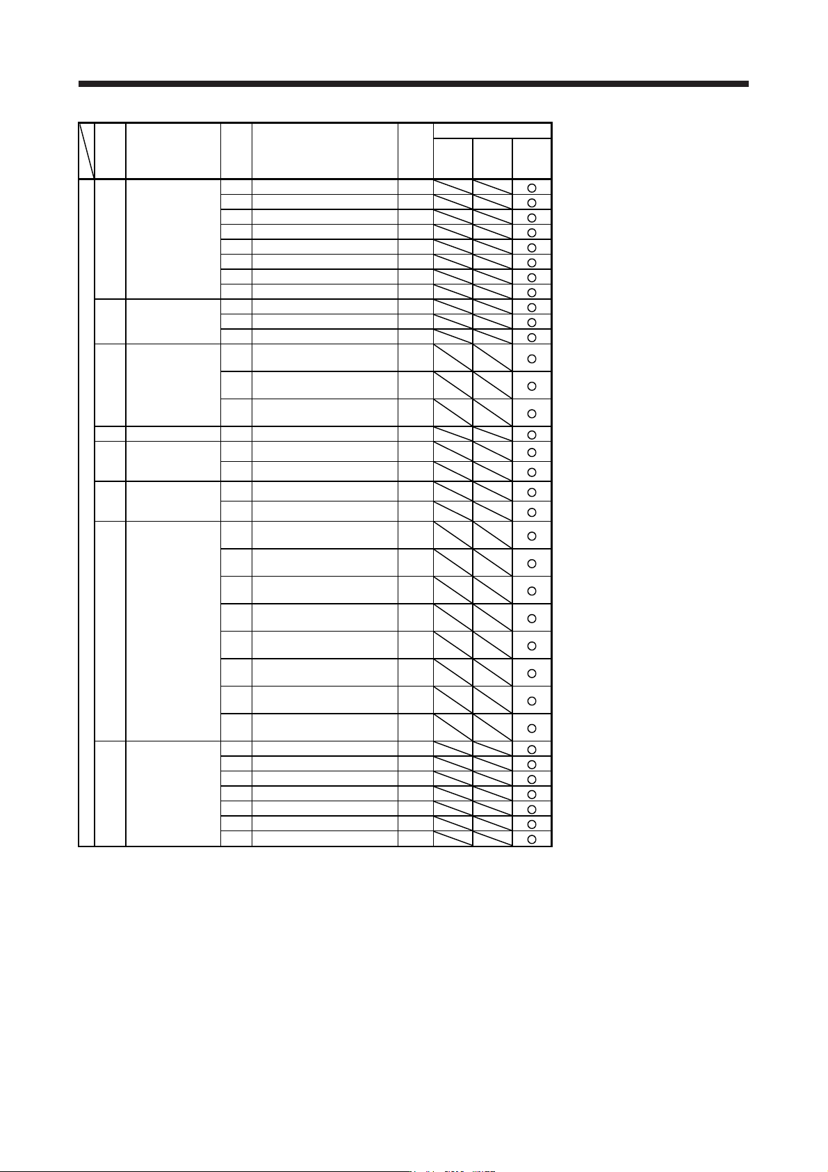
No. Name
Detail
No.
Detail name
Stop
method
(Note
2, 3)
Alarm deactivation
Alarm
reset
CPU
reset
Cycling
the
power
Alarm
17.1 Board error 1 DB
17.3 Board error 2 DB
17.4 Board error 3 DB
17 Board error
17.5 Board error 4 DB
17.6 Board error 5 DB
17.7 Board error 7 DB
17.8 Board error 6 (Note 6) EDB
17.9 Board error 8 DB
Memory error 3
(Flash-ROM)
19.1 Flash-ROM error 1 DB
19 19.2 Flash-ROM error 2 DB
19.3 Flash-ROM error 3 DB
1A.1
Servo motor combination error
1
DB
1A
Servo motor
combination error
1A.2
Servo motor control mode
combination error
DB
1A.4
Servo motor combination error
2
DB
1B Converter error 1B.1 Converter unit error DB
1E
Encoder initial
communication
error 2
1E.1 Encoder malfunction DB
1E.2 Load-side encoder malfunction DB
1F
Encoder initial
communication
error 3
1F.1 Incompatible encoder DB
1F.2 Incompatible load-side encoder DB
20.1
Encoder normal communication
- Receive data error 1
EDB
20.2
Encoder normal communication
- Receive data error 2
EDB
20.3
Encoder normal communication
- Receive data error 3
EDB
20
Encoder normal
communication
error 1
20.5
Encoder normal communication
- Transmission data error 1
EDB
20.6
Encoder normal communication
- Transmission data error 2
EDB
20.7
Encoder normal communication
- Transmission data error 3
EDB
20.9
Encoder normal communication
- Receive data error 4
EDB
20.A
Encoder normal communication
- Receive data error 5
EDB
21.1 Encoder data error 1 EDB
21.2 Encoder data update error EDB
Encoder normal
communication
error 2
21.3 Encoder data waveform error EDB
21 21.4 Encoder non-signal error EDB
21.5 Encoder hardware error 1 EDB
21.6 Encoder hardware error 2 EDB
21.9 Encoder data error 2 EDB